해야될 건 많은데 너무 오래걸리니까
좀 간단하게 정리해야지
4. Xor
Xor 게이트는 nand 4개로, nand+or+and로 만들수 있다.
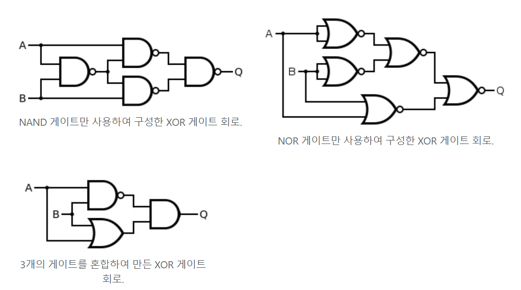
여기서는 nand + or + and로 해보자
CHIP Xor {
    IN a, b;
    OUT out;

    PARTS:
    Nand(a=a, b=b, out=nandOut);
    Or(a=a,b=b,out=orOut);
    And(a=nandOut, b=orOut, out=out);
}

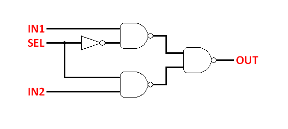
5. Multiplexer
- (1비트) 멀티플렉서는 입력들 중에 하나를 선택하여 출력으로 내보낸다.
- 입력으로 a, b 그리고 입력 선택을 위한 sel 단자, 출력으로 out 단자가 있다.
- sel이 0이면 출력은 a, 아니면 b를 출력하도록 구현한다.
- 아래는 기본 논리게이트로 구현한 먹스
CHIP Mux {
IN a, b, sel;
OUT out;
PARTS:
// Put your code here:
Not(in=sel, out=selNot);
Nand(a=a, b=selNot, out=outNandA);
Nand(a=sel, b= b, out=outNandB);
Nand(a=outNandA, b=outNandB, out=out);
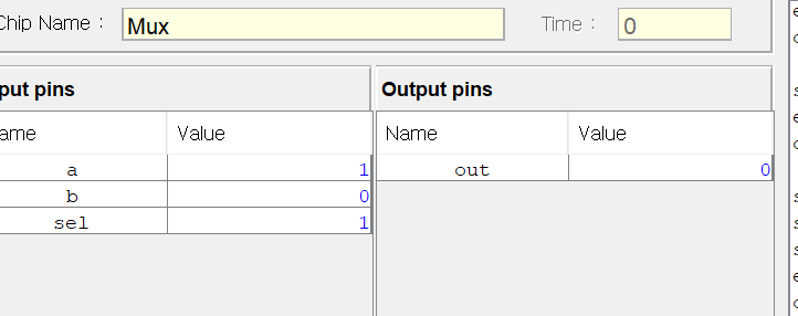
}실행 결과를 보면
- a = 1, b = 0, sel = 1일때, b의 값을 선택하여 출력이 0이 나오는걸 알수있다.
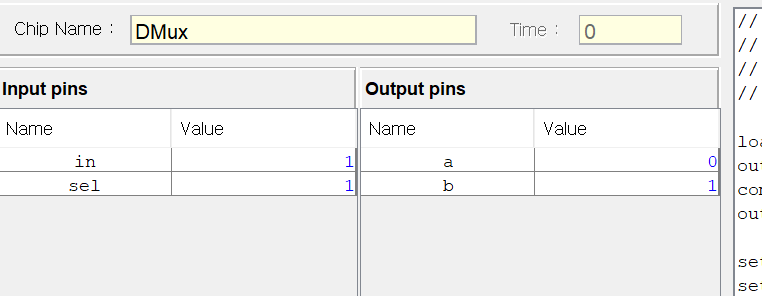
6. Demultiplexer
- 1비트 디멀티플렉서는 입력으로 in, sel, 출력은 a, b가 된다.
- 동작은 sel의 값에 따라 in의 값을 a(sel==0), b(sell==1)로 보낸다.
- 선택받지 못한 출력단자는 0을 출력한다.

CHIP DMux {
    IN in, sel;
    OUT a, b;

    PARTS:
    // Put your code here:
    Not(in =sel, out=selNot);
    And(a=in, b=selNot, out=a);
    And(a=in, b=sel, out=b);
}
dmux의 경우 in = 1, sel = 1일때 b 단자에서 1 출력하는걸 볼수있다.
* 멀티 비트 HDL
- 이제 멀티 비트를 다루는 논리 회로를 구현해야 한다.
- 책에 따르면 내부 버스 핀을 연결하는 경우와 참값 거짓값을 내보내는 경우가 나온다.
내부 핀 입력 : chipPart1(..., x[i]= u, ...); chipPart2(..., x[i..j]=v, ...);
참/거짓값 입력 : chipPart(..., x[0..2] = true, ..., x[6..7] = true, ...);
* 하지만 이 내용은 멀티 비트 논리 회로를 사용할때 필요하고, 멀티비트 논리회로를 만들때는 여러개를 해줘야될거같다..
** 16bit 논리회로 구현하는 이유
- 이 책의 3장인가? 4장쯤에 보면 hack 컴퓨터는 16비트씩 데이터를 처리하고, 레지스터 한개가 16비트를 차지한다.
7. Multi-bit Not(16bit)
이전에 이미 Not게이트를 구현한걸 위 내용 참고해서 16개를 사용해서 16비트 Not게이트를 만들었다.
CHIP Not16 {
    IN in[16];
    OUT out[16];

    PARTS:
    Not(in=in[0], out=out[0]);
    Not(in=in[1], out=out[1]);
    Not(in=in[2], out=out[2]);
    Not(in=in[3], out=out[3]);
    Not(in=in[4], out=out[4]);
    Not(in=in[5], out=out[5]);
    Not(in=in[6], out=out[6]);
    Not(in=in[7], out=out[7]);
    Not(in=in[8], out=out[8]);
    Not(in=in[9], out=out[9]);
    Not(in=in[10], out=out[10]);
    Not(in=in[11], out=out[11]);
    Not(in=in[12], out=out[12]);
    Not(in=in[13], out=out[13]);
    Not(in=in[14], out=out[14]);
    Not(in=in[15], out=out[15]);
}
* 좌측은 10진수 우측은 2진수, 음수는 2의 보수
이전의 Not 게이트 연산때는 0아니면 1만 나왔는데, 이제는 16비트를 다루면서 십진수로 변환되어 나오고 있다.
아래의 분홍색으로 표시한 부분일때의 경우 %B11111111111111같은 식으로 입력이 됬는데,
좌측의 입력 핀에는 -1이 입력된 것으로 나오고 있다.
아마 2진수 1을 2의 보수를 취해 음수로 표현해서 그런것 같다.
2진수 1 = B00000000001
1의 보수로 음수 표현한다면 -1 =B111111111110 같은 식일것이고
2의 보수로 음수 표현한다면 -1 =B111111111111 이 된다.
그래서 아래의 2진수 입력값이 10진수로 -1이 된다.

8. Multi-bit And(16bit)
9. Multi-bit Or(16bit)
그냥 and, or는 and hdl 작성후 복사해서 파트 이름만 or로 바꿔서 만들었다.
CHIP And16 {
    IN a[16], b[16];
    OUT out[16];

    PARTS:
    And(a=a[0], b=b[0], out=out[0]);
    And(a=a[1], b=b[1], out=out[1]);
    And(a=a[2], b=b[2], out=out[2]);
    And(a=a[3], b=b[3], out=out[3]);
    And(a=a[4], b=b[4], out=out[4]);
    And(a=a[5], b=b[5], out=out[5]);
    And(a=a[6], b=b[6], out=out[6]);
    And(a=a[7], b=b[7], out=out[7]);
    And(a=a[8], b=b[8], out=out[8]);
    And(a=a[9], b=b[9], out=out[9]);
    And(a=a[10], b=b[10], out=out[10]);
    And(a=a[11], b=b[11], out=out[11]);
    And(a=a[12], b=b[12], out=out[12]);
    And(a=a[13], b=b[13], out=out[13]);
    And(a=a[14], b=b[14], out=out[14]);
    And(a=a[15], b=b[15], out=out[15]);
}
CHIP Or16 {
    IN a[16], b[16];
    OUT out[16];

    PARTS:
    Or(a=a[0], b=b[0], out=out[0]);
    Or(a=a[1], b=b[1], out=out[1]);
    Or(a=a[2], b=b[2], out=out[2]);
    Or(a=a[3], b=b[3], out=out[3]);
    Or(a=a[4], b=b[4], out=out[4]);
    Or(a=a[5], b=b[5], out=out[5]);
    Or(a=a[6], b=b[6], out=out[6]);
    Or(a=a[7], b=b[7], out=out[7]);
    Or(a=a[8], b=b[8], out=out[8]);
    Or(a=a[9], b=b[9], out=out[9]);
    Or(a=a[10], b=b[10], out=out[10]);
    Or(a=a[11], b=b[11], out=out[11]);
    Or(a=a[12], b=b[12], out=out[12]);
    Or(a=a[13], b=b[13], out=out[13]);
    Or(a=a[14], b=b[14], out=out[14]);
    Or(a=a[15], b=b[15], out=out[15]);
}
10. Multi-bit multiplexer(16bit)
- Mux도 동일하게 16줄짜리 파트 내용 복붙해서 이름만 바꾸려 했는데, sel이 있는걸 잊었다. sel도 추가하자.
CHIP Mux16 {
    IN a[16], b[16], sel;
    OUT out[16];

    PARTS:
    Mux(a=a[0], b=b[0], sel=sel, out=out[0]);
    Mux(a=a[1], b=b[1], sel=sel, out=out[1]);
    Mux(a=a[2], b=b[2], sel=sel, out=out[2]);
    Mux(a=a[3], b=b[3], sel=sel, out=out[3]);
    Mux(a=a[4], b=b[4], sel=sel, out=out[4]);
    Mux(a=a[5], b=b[5], sel=sel, out=out[5]);
    Mux(a=a[6], b=b[6], sel=sel, out=out[6]);
    Mux(a=a[7], b=b[7], sel=sel, out=out[7]);
    Mux(a=a[8], b=b[8], sel=sel, out=out[8]);
    Mux(a=a[9], b=b[9], sel=sel, out=out[9]);
    Mux(a=a[10], b=b[10], sel=sel, out=out[10]);
    Mux(a=a[11], b=b[11], sel=sel, out=out[11]);
    Mux(a=a[12], b=b[12], sel=sel, out=out[12]);
    Mux(a=a[13], b=b[13], sel=sel, out=out[13]);
    Mux(a=a[14], b=b[14], sel=sel, out=out[14]);
    Mux(a=a[15], b=b[15], sel=sel, out=out[15]);
}
11. Multi-way Or(8way)
- 이제 multi-way Or 게이트다! 멀티 웨이 뭐라고 적는게 좋을까 . 그냥 or는 입력을 2개받지만 이건 8way 8개 입력을 받는다는게 다르다.
- 8개의 입력다 or연산하면 되니까, or게이트 7개 가지고 다 or연산하면된다.
* 그림 찾다 보니까 nand2tetris.github.io도 있다. 여기에 설명 코드랑 그림 있으니 참고해도 괜찬을듯
https://nand2tetris-hdl.github.io/
HDL API & Gate Design
in[16], load, address[6] out[16]
nand2tetris-hdl.github.io
저기 나오는데로 해도되지만 난 그냥 쉽게 이런 식으로 해보려고한다.
비효율적인것 같긴한데 이해하기 쉬우면 됫지.
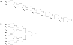
CHIP Or8Way {
    IN in[8];
    OUT out;

    PARTS:
    Or(a=in[0], b=in[1], out=or1);
    Or(a=or1, b=in[2], out=or2);
    Or(a=or2, b=in[3], out=or3);
    Or(a=or3, b=in[4], out=or4);
    Or(a=or4, b=in[5], out=or5);
    Or(a=or5, b=in[6], out=or6);
    Or(a=or6, b=in[7], out=out);
}
12. Multi-way Demultiplexer(4way)
- 이번에는 4way 디먹스다. 4way dmux의 경우 이름 그대로 4개의 길로 출력하는데 출력할 길을 선택하기 위해서 sel 단자 2개가 존재한다.
sel = 11 -> d
sel = 10 -> c
sel = 01 -> b
sel = 00 -> a
셀렉터 단자랑 출력 순서가 좀 햇갈리긴한데 일단 구현해보자.

여기서 and 게이트가 입력 3개를 받으니 고려해서 구현하면 되긴한데 되게 햇갈리네
CHIP DMux4Way {
    IN in, sel[2];
    OUT a, b, c, d;

    PARTS:
    Not(in=sel[1], out=not1);
    Not(in=sel[0], out=not0);
    And(a=in, b=not1, out=and1);
    And(a=and1, b=not0, out=a);

    And(a=in, b=not1, out=and2);
    And(a=and2, b=sel[0], out=b);

    And(a=in, b=sel[1], out=and3);
    And(a=and3, b=not0, out=c);

    And(a=in, b=sel[1], out=and4);
    And(a=and4, b=sel[0], out=d);
}
그래도 생각한데로 in 1일때, sel 값에 따라 생각대로 출력이 되긴한다.

13. Multi-way Demultiplexer(8way)
4출력 디멀티플렉서 만드는것도 머리햇갈리는데 8출력는 어떻게 하나 싶었지만
잠깐 찾아보니 일렉트로 허브란곳에서 4출력 디먹스 2개로 만드는 그림을 올려둿다.

이거 참고해서 만들면 문제없겟지..?
구현하다가 문제가 위의 4출력 디먹스에는 E 단자가 존재한다.
E 단자를 고려하지 않고 hdl을 작성하면 똑같은 디먹스 두개를 사용하게 된다.
    PARTS:
    Not(in=sel[0], out=nota);
    DMux4Way(in=in, sel[1]=sel[1], sel[0]=sel[2]);
    DMux4Way(in=in, sel[1]=sel[1], sel[0]=sel[2]);
위 링크에서 잘보니까 E가 enable이더라
A가 0인경우 not으로 위의 디먹스가 사용되어 위 그림기준으로 Y3 ~ Y0중에서 선택
A가 1일때는 아래의 디먹스가 사용되서 Y7 ~ Y4중 하나를 선택한다.
는건 알겠는데 다시보니까
a, b, c, 출력 단자들 맞춰줘야되서 Dmux4way 두개 쓸게아니라 그냥 구현해야되겠다..
다행인지 불행인지 위의 일렉트로닉스허브에는

어떻게 구현할지 그림도 있다. 이걸 hdl로 써보는게 ㅈ브ㅔㅂㅈ자체ㅐ
CHIP DMux8Way {
    IN in, sel[3];
    OUT a, b, c, d, e, f, g, h;

    PARTS:
    Not(in=sel[2], out=not2);
    Not(in=sel[1], out=not1);
    Not(in=sel[0], out=not0);

    And(a=in, b=not2, out=and12);
    And(a=and12, b=not1, out=and13);
    And(a=and13, b=not0, out=a);

    And(a=in, b=not2, out=and22);
    And(a=and22, b=not1, out=and23);
    And(a=and23, b=sel[0], out=b);

    And(a=in, b=not2, out=and32);
    And(a=and32, b=sel[1], out=and33);
    And(a=and33, b=not0, out=c);

    And(a=in, b=not2, out=and42);
    And(a=and42, b=sel[1], out=and43);
    And(a=and43, b=sel[0], out=d);


    And(a=in, b=sel[2], out=and52);
    And(a=and52, b=not1, out=and53);
    And(a=and53, b=not0, out=e);

    And(a=in, b=sel[2], out=and62);
    And(a=and62, b=not1, out=and63);
    And(a=and63, b=sel[0], out=f);

    And(a=in, b=sel[2], out=and72);
    And(a=and72, b=sel[1], out=and73);
    And(a=and73, b=not0, out=g);

    And(a=in, b=sel[2], out=and82);
    And(a=and82, b=sel[1], out=and83);
    And(a=and83, b=sel[0], out=h);
}
길어서 햇갈리긴 했지만 이상없이 잘동작한다.
이렇게 많이 구현했는데도
2개가 남았다. 시간도 늦었으니 내일해야지.
내일 해도 CPU 까지 할수있을지는 모르겠다..
14. Multi-way/Multi-bit multiplexer(4way 16bit)
15. Multi-way/Multi-bit multiplexer(8way 16bit)
'컴퓨터과학 > 디지털회로' 카테고리의 다른 글
| nand2tetris - 6. hack 기계어와 어셈블리어 1 (0) | 2022.05.16 |
|---|---|
| nand2tetris - 5. 레지스터와 RAM 구현하기 (0) | 2022.05.15 |
| nand2tetris - 4. 반가산기부터 ALU까지 구현하기 (0) | 2022.05.15 |
| nand2tetris - 3. 4way/8way 16bit muletiplexer까지 기본논리회로 마무리 (0) | 2022.05.15 |
| nand2tetris- 1. 소개, NAND 게이트로 Not, And, OR 게이트 구현하기 (0) | 2022.05.14 |