원래 주말에 해야지 생각만하고 계속 질질 미루다
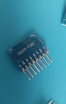
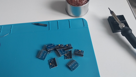
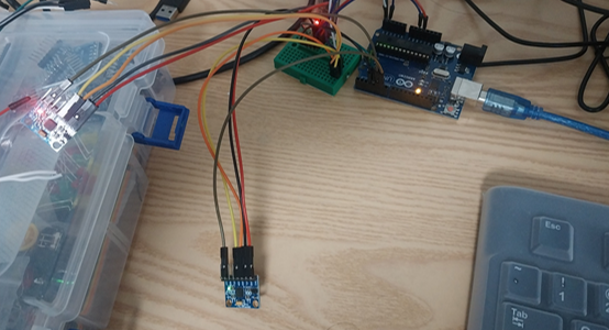
오늘 아침이 되서야 MPU6050 나머지 땜질 다했다.
11개가 준비됬는데
일단 2개만 어떻게하면 동시에 가져올수 있을까 정리
이건 내가 기존에 사용하던 코드인데
MPU6050 mpu;를 여러개 만들어서 일단 정리해야할듯
#include "I2Cdev.h"
#include <SoftwareSerial.h>

#include "MPU6050_6Axis_MotionApps20.h"
#if I2CDEV_IMPLEMENTATION == I2CDEV_ARDUINO_WIRE
    #include "Wire.h"
#endif

// class default I2C address is 0x68
// specific I2C addresses may be passed as a parameter here
// AD0 low = 0x68 (default for SparkFun breakout and InvenSense evaluation board)
// AD0 high = 0x69
MPU6050 mpu;
//MPU6050 mpu(0x69); // <-- use for AD0 high

#define OUTPUT_READABLE_YAWPITCHROLL


#define LED_PIN 13 // (Arduino is 13, Teensy is 11, Teensy++ is 6)
bool blinkState = false;

// MPU control/status vars
bool dmpReady = false;  // set true if DMP init was successful
uint8_t mpuIntStatus;   // holds actual interrupt status byte from MPU
uint8_t devStatus;      // return status after each device operation (0 = success, !0 = error)
uint16_t packetSize;    // expected DMP packet size (default is 42 bytes)
uint16_t fifoCount;     // count of all bytes currently in FIFO
uint8_t fifoBuffer[64]; // FIFO storage buffer

// orientation/motion vars
Quaternion q;           // [w, x, y, z]         quaternion container
VectorInt16 aa;         // [x, y, z]            accel sensor measurements
VectorInt16 aaReal;     // [x, y, z]            gravity-free accel sensor measurements
VectorInt16 aaWorld;    // [x, y, z]            world-frame accel sensor measurements
VectorFloat gravity;    // [x, y, z]            gravity vector
float euler[3];         // [psi, theta, phi]    Euler angle container
float ypr[3];           // [yaw, pitch, roll]   yaw/pitch/roll container and gravity vector

// packet structure for InvenSense teapot demo
uint8_t teapotPacket[14] = { '$', 0x02, 0,0, 0,0, 0,0, 0,0, 0x00, 0x00, '\r', '\n' };


volatile bool mpuInterrupt = false;     // indicates whether MPU interrupt pin has gone high
void dmpDataReady() {
    mpuInterrupt = true;
}


//RXD3, TXD4
SoftwareSerial BTSerial(4, 3);

void setup() {
    BTSerial.begin(9600);

    #if I2CDEV_IMPLEMENTATION == I2CDEV_ARDUINO_WIRE
        Wire.begin();
        TWBR = 24; // 400kHz I2C clock (200kHz if CPU is 8MHz)
    #elif I2CDEV_IMPLEMENTATION == I2CDEV_BUILTIN_FASTWIRE
        Fastwire::setup(400, true);
    #endif

    while (!BTSerial); // wait for Leonardo enumeration, others continue immediately

    // initialize device
    BTSerial.println(F("Initializing I2C devices..."));
    mpu.initialize();
    //pinMode(INTERRUPT_PIN, INPUT);

    // verify connection
    BTSerial.println(F("Testing device connections..."));
    BTSerial.println(mpu.testConnection() ? F("MPU6050 connection successful") : F("MPU6050 connection failed"));

    // load and configure the DMP
    BTSerial.println(F("Initializing DMP..."));
    devStatus = mpu.dmpInitialize();

    // supply your own gyro offsets here, scaled for min sensitivity
    mpu.setXGyroOffset(220);
    mpu.setYGyroOffset(76);
    mpu.setZGyroOffset(-85);
    mpu.setZAccelOffset(1788); // 1688 factory default for my test chip

    // make sure it worked (returns 0 if so)
    if (devStatus == 0) {
        // turn on the DMP, now that it's ready
        BTSerial.println(F("Enabling DMP..."));
        mpu.setDMPEnabled(true);

        // enable Arduino interrupt detection
        BTSerial.println(F("Enabling interrupt detection (Arduino external interrupt 0)..."));
        attachInterrupt(0, dmpDataReady, RISING);
        //attachInterrupt(digitalPinToInterrupt(INTERRUPT_PIN), dmpDataReady, RISING);

        mpuIntStatus = mpu.getIntStatus();

        // set our DMP Ready flag so the main loop() function knows it's okay to use it
        BTSerial.println(F("DMP ready! Waiting for first interrupt..."));
        dmpReady = true;

        // get expected DMP packet size for later comparison
        packetSize = mpu.dmpGetFIFOPacketSize();
    } else {
        BTSerial.print(F("DMP Initialization failed (code "));
        BTSerial.print(devStatus);
        BTSerial.println(F(")"));
    }
}


void loop() {
    // if programming failed, don't try to do anything
    if (!dmpReady) return;

    // wait for MPU interrupt or extra packet(s) available
    while (!mpuInterrupt && fifoCount < packetSize) {
    }

    // reset interrupt flag and get INT_STATUS byte
    mpuInterrupt = false;
    mpuIntStatus = mpu.getIntStatus();

    // get current FIFO count
    fifoCount = mpu.getFIFOCount();

    // check for overflow (this should never happen unless our code is too inefficient)
    if ((mpuIntStatus & 0x10) || fifoCount == 1024) {
        // reset so we can continue cleanly
        mpu.resetFIFO();
        //BTSerial.println(F("FIFO overflow!"));

    // otherwise, check for DMP data ready interrupt (this should happen frequently)
    } else if (mpuIntStatus & 0x02) {
        // wait for correct available data length, should be a VERY short wait
        while (fifoCount < packetSize) fifoCount = mpu.getFIFOCount();

        // read a packet from FIFO
        mpu.getFIFOBytes(fifoBuffer, packetSize);

        // track FIFO count here in case there is > 1 packet available
        // (this lets us immediately read more without waiting for an interrupt)
        fifoCount -= packetSize;

        #ifdef OUTPUT_READABLE_YAWPITCHROLL
            // display Euler angles in degrees
            mpu.dmpGetQuaternion(&q, fifoBuffer);
            mpu.dmpGetGravity(&gravity, &q);
            mpu.dmpGetYawPitchRoll(ypr, &q, &gravity);
            BTSerial.print(int(ypr[0] * 180/M_PI));
            BTSerial.print(",");
            BTSerial.print(int(ypr[1] * 180/M_PI));
            BTSerial.print(",");
            BTSerial.print(int(ypr[2] * 180/M_PI));
            BTSerial.print("/");
        #endif
    }
    //delay(30);
    delay(100);

}
하려다가 mpu 기본주소가 0x68인데
ad0핀으로 어떻게 조정하는지부터 찾아봐야겟다.
이제 이해한게 mpu6050은 ad0로 주소를 2가지 경우로만 설정못한다고 한다.
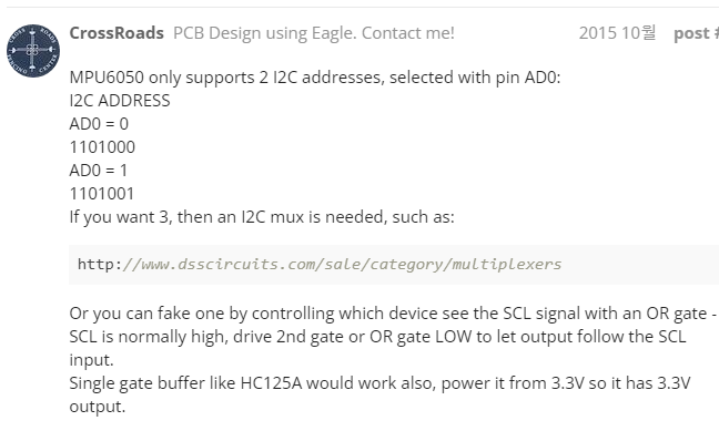
저 내용 밑에보면
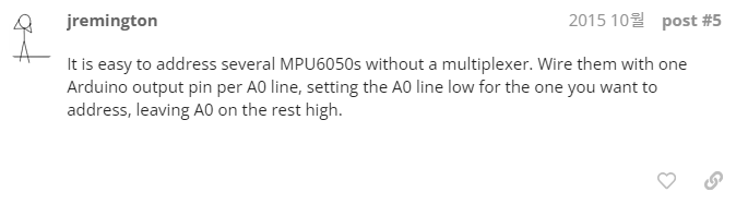
jremington이란 사람이
mpu6050 여러개 연결해서
가져올것만 ad0 핀일 low하고 나머지는 high로 설정해주면 된다고 설명한다.
이게 괜찬은 방법인진 모르겟지만 일단 대충해보자
일단 지레밍턴? 말대로 해서 한번 만들어봤다.
프리징 같은걸로 우노보드랑 모듈들 배선 정리해서 올리고싶긴한데
유료화되서 쓰기도 힘들고
다른 적당한걸 못찾아서 그냥 만들기만함.
#include "I2Cdev.h"
#include <SoftwareSerial.h>

#include "MPU6050_6Axis_MotionApps20.h"
#if I2CDEV_IMPLEMENTATION == I2CDEV_ARDUINO_WIRE
    #include "Wire.h"
#endif

// class default I2C address is 0x68
// specific I2C addresses may be passed as a parameter here
// AD0 low = 0x68 (default for SparkFun breakout and InvenSense evaluation board)
// AD0 high = 0x69
MPU6050 mpu;
//MPU6050 mpu(0x69); // <-- use for AD0 high

#define OUTPUT_READABLE_YAWPITCHROLL


#define LED_PIN 13 // (Arduino is 13, Teensy is 11, Teensy++ is 6)
bool blinkState = false;

// MPU control/status vars
bool dmpReady = false;  // set true if DMP init was successful
uint8_t mpuIntStatus;   // holds actual interrupt status byte from MPU
uint8_t devStatus;      // return status after each device operation (0 = success, !0 = error)
uint16_t packetSize;    // expected DMP packet size (default is 42 bytes)
uint16_t fifoCount;     // count of all bytes currently in FIFO
uint8_t fifoBuffer[64]; // FIFO storage buffer

// orientation/motion vars
Quaternion q;           // [w, x, y, z]         quaternion container
VectorInt16 aa;         // [x, y, z]            accel sensor measurements
VectorInt16 aaReal;     // [x, y, z]            gravity-free accel sensor measurements
VectorInt16 aaWorld;    // [x, y, z]            world-frame accel sensor measurements
VectorFloat gravity;    // [x, y, z]            gravity vector
float euler[3];         // [psi, theta, phi]    Euler angle container
float ypr[3];           // [yaw, pitch, roll]   yaw/pitch/roll container and gravity vector

// packet structure for InvenSense teapot demo
uint8_t teapotPacket[14] = { '$', 0x02, 0,0, 0,0, 0,0, 0,0, 0x00, 0x00, '\r', '\n' };


volatile bool mpuInterrupt = false;     // indicates whether MPU interrupt pin has gone high
void dmpDataReady() {
    mpuInterrupt = true;
}


//RXD3, TXD4
SoftwareSerial BTSerial(4, 3);
int mpuPinNums[] = {5, 6};


void InitMPU(int pinNum);
void SendData(int pinNum);

void setup() {
  pinMode(5, OUTPUT);//MPU #1
  pinMode(6, OUTPUT);//MPU #2

  Serial.begin(115200);

  #if I2CDEV_IMPLEMENTATION == I2CDEV_ARDUINO_WIRE
      Wire.begin();
      TWBR = 24; // 400kHz I2C clock (200kHz if CPU is 8MHz)
  #elif I2CDEV_IMPLEMENTATION == I2CDEV_BUILTIN_FASTWIRE
      Fastwire::setup(400, true);
  #endif

  while (!Serial); // wait for Leonardo enumeration, others continue immediately

  for (int i = 0; i<2; i++)
    InitMPU(mpuPinNums[i]);
}


void loop() {
  for (int i = 0; i<2; i++)
    SendData(mpuPinNums[i]);

  Serial.println("");
  delay(100);
}


void InitMPU(int pinNum)
{
  for (int i = 0; i < 2; i++)
  {
    if (mpuPinNums[i] == pinNum)
      digitalWrite(pinNum, LOW);  //set selected mpu6050 addr 0x68
    else
      digitalWrite(mpuPinNums[i], HIGH);  //set other mpu6050 addr 0x69
  }
  Serial.print("start init pin ");
  Serial.println(pinNum);


  // initialize device
  mpu.initialize();

  // verify connection
  Serial.println(F("Testing device connections..."));
  Serial.println(mpu.testConnection() ? F("MPU6050 connection successful") : F("MPU6050 connection failed"));

  // load and configure the DMP
  Serial.println(F("Initializing DMP..."));
  devStatus = mpu.dmpInitialize();

  // supply your own gyro offsets here, scaled for min sensitivity
  mpu.setXGyroOffset(220);
  mpu.setYGyroOffset(76);
  mpu.setZGyroOffset(-85);
  mpu.setZAccelOffset(1788); // 1688 factory default for my test chip

  // make sure it worked (returns 0 if so)
  if (devStatus == 0) {
      // turn on the DMP, now that it's ready
      Serial.println(F("Enabling DMP..."));
      mpu.setDMPEnabled(true);

      // enable Arduino interrupt detection
      Serial.println(F("Enabling interrupt detection (Arduino external interrupt 0)..."));
      attachInterrupt(0, dmpDataReady, RISING);
      //attachInterrupt(digitalPinToInterrupt(INTERRUPT_PIN), dmpDataReady, RISING);

      mpuIntStatus = mpu.getIntStatus();

      // set our DMP Ready flag so the main loop() function knows it's okay to use it
      Serial.println(F("DMP ready! Waiting for first interrupt..."));
      dmpReady = true;

      // get expected DMP packet size for later comparison
      packetSize = mpu.dmpGetFIFOPacketSize();
  } else {
      Serial.print(F("DMP Initialization failed (code "));
      Serial.print(devStatus);
      Serial.println(F(")"));
  }
}

void SendData(int pinNum)
{
    for (int i = 0; i < 2; i++)
    {
      if (mpuPinNums[i] == pinNum)
        digitalWrite(mpuPinNums[i], LOW);  //set selected mpu6050 addr 0x68
      else
        digitalWrite(mpuPinNums[i], HIGH);  //set other mpu6050 addr 0x69
    }

    // if programming failed, don't try to do anything
    if (!dmpReady) return;

    // wait for MPU interrupt or extra packet(s) available
    while (!mpuInterrupt && fifoCount < packetSize) {
    }

    // reset interrupt flag and get INT_STATUS byte
    mpuInterrupt = false;
    mpuIntStatus = mpu.getIntStatus();

    // get current FIFO count
    fifoCount = mpu.getFIFOCount();

    // check for overflow (this should never happen unless our code is too inefficient)
    if ((mpuIntStatus & 0x10) || fifoCount == 1024) {
        // reset so we can continue cleanly
        mpu.resetFIFO();

    // otherwise, check for DMP data ready interrupt (this should happen frequently)
    } else if (mpuIntStatus & 0x02) {
        // wait for correct available data length, should be a VERY short wait
        while (fifoCount < packetSize) fifoCount = mpu.getFIFOCount();

        // read a packet from FIFO
        mpu.getFIFOBytes(fifoBuffer, packetSize);

        // track FIFO count here in case there is > 1 packet available
        // (this lets us immediately read more without waiting for an interrupt)
        fifoCount -= packetSize;

        #ifdef OUTPUT_READABLE_YAWPITCHROLL
            // display Euler angles in degrees
            mpu.dmpGetQuaternion(&q, fifoBuffer);
            mpu.dmpGetGravity(&gravity, &q);
            mpu.dmpGetYawPitchRoll(ypr, &q, &gravity);
            Serial.print(pinNum);
            Serial.print(":");
            Serial.print(int(ypr[0] * 180/M_PI));
            Serial.print(",");
            Serial.print(int(ypr[1] * 180/M_PI));
            Serial.print(",");
            Serial.print(int(ypr[2] * 180/M_PI));
            Serial.print("/");
        #endif
    }
}
기존의 초기화, 각 가져오는 코드는 따로빼고
AD0 핀들 output 설정
int mpuPinNums[] = {5, 6};

void InitMPU(int pinNum);
void SendData(int pinNum);

void setup() {
  pinMode(5, OUTPUT);//MPU #1
  pinMode(6, OUTPUT);//MPU #2

  Serial.begin(115200);

  #if I2CDEV_IMPLEMENTATION == I2CDEV_ARDUINO_WIRE
      Wire.begin();
      TWBR = 24; // 400kHz I2C clock (200kHz if CPU is 8MHz)
  #elif I2CDEV_IMPLEMENTATION == I2CDEV_BUILTIN_FASTWIRE
      Fastwire::setup(400, true);
  #endif

  while (!Serial); // wait for Leonardo enumeration, others continue immediately

  for (int i = 0; i<2; i++)
    InitMPU(mpuPinNums[i]);
}
초기화 코드에서는
모든 mpu를 돌아가면서 초기화하는데
선택된 mpu만 주소를 0x68로 설정하고 수행
나머지는 초기화전 0x69로 설정
void InitMPU(int pinNum)
{
  for (int i = 0; i < 2; i++)
  {
    if (mpuPinNums[i] == pinNum)
      digitalWrite(pinNum, LOW);  //set selected mpu6050 addr 0x68
    else
      digitalWrite(mpuPinNums[i], HIGH);  //set other mpu6050 addr 0x69
  }
  Serial.print("start init pin ");
  Serial.println(pinNum);


  // initialize device
  mpu.initialize();

  // verify connection
  Serial.println(F("Testing device connections..."));
  Serial.println(mpu.testConnection() ? F("MPU6050 connection successful") : F("MPU6050 connection failed"));

  // load and configure the DMP
  Serial.println(F("Initializing DMP..."));
  devStatus = mpu.dmpInitialize();

  // supply your own gyro offsets here, scaled for min sensitivity
  mpu.setXGyroOffset(220);
  mpu.setYGyroOffset(76);
  mpu.setZGyroOffset(-85);
  mpu.setZAccelOffset(1788); // 1688 factory default for my test chip

  // make sure it worked (returns 0 if so)
  if (devStatus == 0) {
      // turn on the DMP, now that it's ready
      Serial.println(F("Enabling DMP..."));
      mpu.setDMPEnabled(true);

      // enable Arduino interrupt detection
      Serial.println(F("Enabling interrupt detection (Arduino external interrupt 0)..."));
      attachInterrupt(0, dmpDataReady, RISING);
      //attachInterrupt(digitalPinToInterrupt(INTERRUPT_PIN), dmpDataReady, RISING);

      mpuIntStatus = mpu.getIntStatus();

      // set our DMP Ready flag so the main loop() function knows it's okay to use it
      Serial.println(F("DMP ready! Waiting for first interrupt..."));
      dmpReady = true;

      // get expected DMP packet size for later comparison
      packetSize = mpu.dmpGetFIFOPacketSize();
  } else {
      Serial.print(F("DMP Initialization failed (code "));
      Serial.print(devStatus);
      Serial.println(F(")"));
  }
}
루프의 경우 각 mpu 돌아가면서 각 출력하고 딜레이 주는식으로 정리
void loop() {
  for (int i = 0; i<2; i++)
    SendData(mpuPinNums[i]);

  Serial.println("");
  delay(50);
}
senddata의 경우
초기화때와 마찬가지로 선택된 mpu만 가져오도록 설정
void SendData(int pinNum)
{
    for (int i = 0; i < 2; i++)
    {
      if (mpuPinNums[i] == pinNum)
        digitalWrite(mpuPinNums[i], LOW);  //set selected mpu6050 addr 0x68
      else
        digitalWrite(mpuPinNums[i], HIGH);  //set other mpu6050 addr 0x69
    }

    // if programming failed, don't try to do anything
    if (!dmpReady) return;

    // wait for MPU interrupt or extra packet(s) available
    while (!mpuInterrupt && fifoCount < packetSize) {
    }

    // reset interrupt flag and get INT_STATUS byte
    mpuInterrupt = false;
    mpuIntStatus = mpu.getIntStatus();

    // get current FIFO count
    fifoCount = mpu.getFIFOCount();

    // check for overflow (this should never happen unless our code is too inefficient)
    if ((mpuIntStatus & 0x10) || fifoCount == 1024) {
        // reset so we can continue cleanly
        mpu.resetFIFO();

    // otherwise, check for DMP data ready interrupt (this should happen frequently)
    } else if (mpuIntStatus & 0x02) {
        // wait for correct available data length, should be a VERY short wait
        while (fifoCount < packetSize) fifoCount = mpu.getFIFOCount();

        // read a packet from FIFO
        mpu.getFIFOBytes(fifoBuffer, packetSize);

        // track FIFO count here in case there is > 1 packet available
        // (this lets us immediately read more without waiting for an interrupt)
        fifoCount -= packetSize;

        #ifdef OUTPUT_READABLE_YAWPITCHROLL
            // display Euler angles in degrees
            mpu.dmpGetQuaternion(&q, fifoBuffer);
            mpu.dmpGetGravity(&gravity, &q);
            mpu.dmpGetYawPitchRoll(ypr, &q, &gravity);
            Serial.print(pinNum);
            Serial.print(":");
            Serial.print(int(ypr[0] * 180/M_PI));
            Serial.print(",");
            Serial.print(int(ypr[1] * 180/M_PI));
            Serial.print(",");
            Serial.print(int(ypr[2] * 180/M_PI));
            Serial.print("/");
        #endif
    }
}
이 코드는 배터리가 아닌 PC전원으로 쓰면서
115200 시리얼 통신으로 가져와 쓰드록 정리
#include "I2Cdev.h"
#include <SoftwareSerial.h>

#include "MPU6050_6Axis_MotionApps20.h"
#if I2CDEV_IMPLEMENTATION == I2CDEV_ARDUINO_WIRE
    #include "Wire.h"
#endif

// class default I2C address is 0x68
// specific I2C addresses may be passed as a parameter here
// AD0 low = 0x68 (default for SparkFun breakout and InvenSense evaluation board)
// AD0 high = 0x69
MPU6050 mpu;
//MPU6050 mpu(0x69); // <-- use for AD0 high

#define OUTPUT_READABLE_YAWPITCHROLL


#define LED_PIN 13 // (Arduino is 13, Teensy is 11, Teensy++ is 6)
bool blinkState = false;

// MPU control/status vars
bool dmpReady = false;  // set true if DMP init was successful
uint8_t mpuIntStatus;   // holds actual interrupt status byte from MPU
uint8_t devStatus;      // return status after each device operation (0 = success, !0 = error)
uint16_t packetSize;    // expected DMP packet size (default is 42 bytes)
uint16_t fifoCount;     // count of all bytes currently in FIFO
uint8_t fifoBuffer[64]; // FIFO storage buffer

// orientation/motion vars
Quaternion q;           // [w, x, y, z]         quaternion container
VectorInt16 aa;         // [x, y, z]            accel sensor measurements
VectorInt16 aaReal;     // [x, y, z]            gravity-free accel sensor measurements
VectorInt16 aaWorld;    // [x, y, z]            world-frame accel sensor measurements
VectorFloat gravity;    // [x, y, z]            gravity vector
float euler[3];         // [psi, theta, phi]    Euler angle container
float ypr[3];           // [yaw, pitch, roll]   yaw/pitch/roll container and gravity vector

// packet structure for InvenSense teapot demo
uint8_t teapotPacket[14] = { '$', 0x02, 0,0, 0,0, 0,0, 0,0, 0x00, 0x00, '\r', '\n' };


volatile bool mpuInterrupt = false;     // indicates whether MPU interrupt pin has gone high
void dmpDataReady() {
    mpuInterrupt = true;
}


//RXD3, TXD4
SoftwareSerial BTSerial(4, 3);
int mpuPinNums[] = {5, 6};

void InitMPU(int pinNum);
void SendData(int pinNum);

void setup() {
  pinMode(5, OUTPUT);//MPU #1
  pinMode(6, OUTPUT);//MPU #2

  Serial.begin(115200);

  #if I2CDEV_IMPLEMENTATION == I2CDEV_ARDUINO_WIRE
      Wire.begin();
      TWBR = 24; // 400kHz I2C clock (200kHz if CPU is 8MHz)
  #elif I2CDEV_IMPLEMENTATION == I2CDEV_BUILTIN_FASTWIRE
      Fastwire::setup(400, true);
  #endif

  while (!Serial); // wait for Leonardo enumeration, others continue immediately

  for (int i = 0; i<2; i++)
    InitMPU(mpuPinNums[i]);
}


void loop() {
  for (int i = 0; i<2; i++)
    SendData(mpuPinNums[i]);

  Serial.println("");
  delay(50);
}


void InitMPU(int pinNum)
{
  for (int i = 0; i < 2; i++)
  {
    if (mpuPinNums[i] == pinNum)
      digitalWrite(pinNum, LOW);  //set selected mpu6050 addr 0x68
    else
      digitalWrite(mpuPinNums[i], HIGH);  //set other mpu6050 addr 0x69
  }
  Serial.print("start init pin ");
  Serial.println(pinNum);


  // initialize device
  mpu.initialize();

  // verify connection
  Serial.println(F("Testing device connections..."));
  Serial.println(mpu.testConnection() ? F("MPU6050 connection successful") : F("MPU6050 connection failed"));

  // load and configure the DMP
  Serial.println(F("Initializing DMP..."));
  devStatus = mpu.dmpInitialize();

  // supply your own gyro offsets here, scaled for min sensitivity
  mpu.setXGyroOffset(220);
  mpu.setYGyroOffset(76);
  mpu.setZGyroOffset(-85);
  mpu.setZAccelOffset(1788); // 1688 factory default for my test chip

  // make sure it worked (returns 0 if so)
  if (devStatus == 0) {
      // turn on the DMP, now that it's ready
      Serial.println(F("Enabling DMP..."));
      mpu.setDMPEnabled(true);

      // enable Arduino interrupt detection
      Serial.println(F("Enabling interrupt detection (Arduino external interrupt 0)..."));
      attachInterrupt(0, dmpDataReady, RISING);
      //attachInterrupt(digitalPinToInterrupt(INTERRUPT_PIN), dmpDataReady, RISING);

      mpuIntStatus = mpu.getIntStatus();

      // set our DMP Ready flag so the main loop() function knows it's okay to use it
      Serial.println(F("DMP ready! Waiting for first interrupt..."));
      dmpReady = true;

      // get expected DMP packet size for later comparison
      packetSize = mpu.dmpGetFIFOPacketSize();
  } else {
      Serial.print(F("DMP Initialization failed (code "));
      Serial.print(devStatus);
      Serial.println(F(")"));
  }
}

void SendData(int pinNum)
{
    for (int i = 0; i < 2; i++)
    {
      if (mpuPinNums[i] == pinNum)
        digitalWrite(mpuPinNums[i], LOW);  //set selected mpu6050 addr 0x68
      else
        digitalWrite(mpuPinNums[i], HIGH);  //set other mpu6050 addr 0x69
    }

    // if programming failed, don't try to do anything
    if (!dmpReady) return;

    // wait for MPU interrupt or extra packet(s) available
    while (!mpuInterrupt && fifoCount < packetSize) {
    }

    // reset interrupt flag and get INT_STATUS byte
    mpuInterrupt = false;
    mpuIntStatus = mpu.getIntStatus();

    // get current FIFO count
    fifoCount = mpu.getFIFOCount();

    // check for overflow (this should never happen unless our code is too inefficient)
    if ((mpuIntStatus & 0x10) || fifoCount == 1024) {
        // reset so we can continue cleanly
        mpu.resetFIFO();

    // otherwise, check for DMP data ready interrupt (this should happen frequently)
    } else if (mpuIntStatus & 0x02) {
        // wait for correct available data length, should be a VERY short wait
        while (fifoCount < packetSize) fifoCount = mpu.getFIFOCount();

        // read a packet from FIFO
        mpu.getFIFOBytes(fifoBuffer, packetSize);

        // track FIFO count here in case there is > 1 packet available
        // (this lets us immediately read more without waiting for an interrupt)
        fifoCount -= packetSize;

        #ifdef OUTPUT_READABLE_YAWPITCHROLL
            // display Euler angles in degrees
            mpu.dmpGetQuaternion(&q, fifoBuffer);
            mpu.dmpGetGravity(&gravity, &q);
            mpu.dmpGetYawPitchRoll(ypr, &q, &gravity);
            Serial.print(pinNum);
            Serial.print(":");
            Serial.print(int(ypr[0] * 180/M_PI));
            Serial.print(",");
            Serial.print(int(ypr[1] * 180/M_PI));
            Serial.print(",");
            Serial.print(int(ypr[2] * 180/M_PI));
            Serial.print("/");
        #endif
    }
}
이번엔 블루투스로 변경
딜레이 100주면 115200 써도 되나모르겟다.
안되서 9600으로 다시진행
#include "I2Cdev.h"
#include <SoftwareSerial.h>

#include "MPU6050_6Axis_MotionApps20.h"
#if I2CDEV_IMPLEMENTATION == I2CDEV_ARDUINO_WIRE
    #include "Wire.h"
#endif

// class default I2C address is 0x68
// specific I2C addresses may be passed as a parameter here
// AD0 low = 0x68 (default for SparkFun breakout and InvenSense evaluation board)
// AD0 high = 0x69
MPU6050 mpu;
//MPU6050 mpu(0x69); // <-- use for AD0 high

#define OUTPUT_READABLE_YAWPITCHROLL


#define LED_PIN 13 // (Arduino is 13, Teensy is 11, Teensy++ is 6)
bool blinkState = false;

// MPU control/status vars
bool dmpReady = false;  // set true if DMP init was successful
uint8_t mpuIntStatus;   // holds actual interrupt status byte from MPU
uint8_t devStatus;      // return status after each device operation (0 = success, !0 = error)
uint16_t packetSize;    // expected DMP packet size (default is 42 bytes)
uint16_t fifoCount;     // count of all bytes currently in FIFO
uint8_t fifoBuffer[64]; // FIFO storage buffer

// orientation/motion vars
Quaternion q;           // [w, x, y, z]         quaternion container
VectorInt16 aa;         // [x, y, z]            accel sensor measurements
VectorInt16 aaReal;     // [x, y, z]            gravity-free accel sensor measurements
VectorInt16 aaWorld;    // [x, y, z]            world-frame accel sensor measurements
VectorFloat gravity;    // [x, y, z]            gravity vector
float euler[3];         // [psi, theta, phi]    Euler angle container
float ypr[3];           // [yaw, pitch, roll]   yaw/pitch/roll container and gravity vector

// packet structure for InvenSense teapot demo
uint8_t teapotPacket[14] = { '$', 0x02, 0,0, 0,0, 0,0, 0,0, 0x00, 0x00, '\r', '\n' };


volatile bool mpuInterrupt = false;     // indicates whether MPU interrupt pin has gone high
void dmpDataReady() {
    mpuInterrupt = true;
}


//RXD3, TXD4
SoftwareSerial BTSerial(4, 3);
int mpuPinNums[] = {5, 6};


void InitMPU(int pinNum);
void SendData(int pinNum);

void setup() {
  pinMode(5, OUTPUT);//MPU #1
  pinMode(6, OUTPUT);//MPU #2

  BTSerial.begin(9600);

  #if I2CDEV_IMPLEMENTATION == I2CDEV_ARDUINO_WIRE
      Wire.begin();
      TWBR = 24; // 400kHz I2C clock (200kHz if CPU is 8MHz)
  #elif I2CDEV_IMPLEMENTATION == I2CDEV_BUILTIN_FASTWIRE
      Fastwire::setup(400, true);
  #endif

  while (!Serial); // wait for Leonardo enumeration, others continue immediately

  InitMPU(5);
  InitMPU(6);
}


void loop() {


  SendData(5);
  SendData(6);
  BTSerial.println("");
  delay(100);
}


void InitMPU(int pinNum)
{
  for (int i = 0; i < 2; i++)
  {
    if (mpuPinNums[i] == pinNum)
      digitalWrite(pinNum, LOW);  //set selected mpu6050 addr 0x68
    else
      digitalWrite(mpuPinNums[i], HIGH);  //set other mpu6050 addr 0x69
  }
  BTSerial.print("start init pin ");
  BTSerial.println(pinNum);


  // initialize device
  mpu.initialize();

  // verify connection
  BTSerial.println(F("Testing device connections..."));
  BTSerial.println(mpu.testConnection() ? F("MPU6050 connection successful") : F("MPU6050 connection failed"));

  // load and configure the DMP
  BTSerial.println(F("Initializing DMP..."));
  devStatus = mpu.dmpInitialize();

  // supply your own gyro offsets here, scaled for min sensitivity
  mpu.setXGyroOffset(220);
  mpu.setYGyroOffset(76);
  mpu.setZGyroOffset(-85);
  mpu.setZAccelOffset(1788); // 1688 factory default for my test chip

  // make sure it worked (returns 0 if so)
  if (devStatus == 0) {
      // turn on the DMP, now that it's ready
      BTSerial.println(F("Enabling DMP..."));
      mpu.setDMPEnabled(true);

      // enable Arduino interrupt detection
      BTSerial.println(F("Enabling interrupt detection (Arduino external interrupt 0)..."));
      attachInterrupt(0, dmpDataReady, RISING);
      //attachInterrupt(digitalPinToInterrupt(INTERRUPT_PIN), dmpDataReady, RISING);

      mpuIntStatus = mpu.getIntStatus();

      // set our DMP Ready flag so the main loop() function knows it's okay to use it
      BTSerial.println(F("DMP ready! Waiting for first interrupt..."));
      dmpReady = true;

      // get expected DMP packet size for later comparison
      packetSize = mpu.dmpGetFIFOPacketSize();
  } else {
      BTSerial.print(F("DMP Initialization failed (code "));
      BTSerial.print(devStatus);
      BTSerial.println(F(")"));
  }
}

void SendData(int pinNum)
{
    for (int i = 0; i < 2; i++)
    {
      if (mpuPinNums[i] == pinNum)
        digitalWrite(mpuPinNums[i], LOW);  //set selected mpu6050 addr 0x68
      else
        digitalWrite(mpuPinNums[i], HIGH);  //set other mpu6050 addr 0x69
    }

    // if programming failed, don't try to do anything
    if (!dmpReady) return;

    // wait for MPU interrupt or extra packet(s) available
    while (!mpuInterrupt && fifoCount < packetSize) {
    }

    // reset interrupt flag and get INT_STATUS byte
    mpuInterrupt = false;
    mpuIntStatus = mpu.getIntStatus();

    // get current FIFO count
    fifoCount = mpu.getFIFOCount();

    // check for overflow (this should never happen unless our code is too inefficient)
    if ((mpuIntStatus & 0x10) || fifoCount == 1024) {
        // reset so we can continue cleanly
        mpu.resetFIFO();

    // otherwise, check for DMP data ready interrupt (this should happen frequently)
    } else if (mpuIntStatus & 0x02) {
        // wait for correct available data length, should be a VERY short wait
        while (fifoCount < packetSize) fifoCount = mpu.getFIFOCount();

        // read a packet from FIFO
        mpu.getFIFOBytes(fifoBuffer, packetSize);

        // track FIFO count here in case there is > 1 packet available
        // (this lets us immediately read more without waiting for an interrupt)
        fifoCount -= packetSize;

        #ifdef OUTPUT_READABLE_YAWPITCHROLL
            // display Euler angles in degrees
            mpu.dmpGetQuaternion(&q, fifoBuffer);
            mpu.dmpGetGravity(&gravity, &q);
            mpu.dmpGetYawPitchRoll(ypr, &q, &gravity);
            BTSerial.print(pinNum);
            BTSerial.print(":");
            BTSerial.print(int(ypr[0] * 180/M_PI));
            BTSerial.print(",");
            BTSerial.print(int(ypr[1] * 180/M_PI));
            BTSerial.print(",");
            BTSerial.print(int(ypr[2] * 180/M_PI));
            BTSerial.print("/");
        #endif
    }
}
아까 유선으로 할때도 그랬지만
종종 데이터가 2개다 출력되지 않고 1개만 출력되는 경우가 생긴다.
조건문에서 생긴 문제같은데
따로 확인해봐야할듯
9600 보드레이트, 100 딜레이줫을때 잘 나온다.
이런식으로 10개까지 늘려도 될것같은데
esp32는 언제쓸까 .
'컴퓨터과학 > 언리얼' 카테고리의 다른 글
| 관성모션 - 12. ESP32 블루투스 사용해보기 (0) | 2024.02.28 |
|---|---|
| 관성모션 - 11. MPU6050 여러 개 써보기(MUX 없이) + 인터럽트 상태 살펴보기 (0) | 2024.02.28 |
| 관성모션 - 9. 관성계 오프셋 조정 x, 다른 모델로 가지고 놀기 (0) | 2024.02.25 |
| 관성모션 - 8. 보간으로 부드럽게 회전 시키기 (0) | 2024.02.24 |
| 관성모션 - 7. 언리얼 블루투스 시리얼로 MPU6050값 받아 액터 제어 (0) | 2024.02.23 |