이전 글에서
MPU6050 YPR 가져와서 블루투스로 통신하는걸 했는데
우노보드때와 다르게
보조베터리 전원을 사용해도 정상적으로 데이터 송신하는걸 확인할수 있었다.
이번 글을 작성하면서 MPU6050 여러개 연결해서 해보려고하는데
AD0로 주소를 두가지만 선택할수 있다보니 이전에 사용한 방법을 그대로하려고한다.
아래 핀맵을 보면
GPIO 번호랑 흰색 박스에 번호가 따로있어서
GPIO 번호를 쓰면 되는지 햇갈리는데
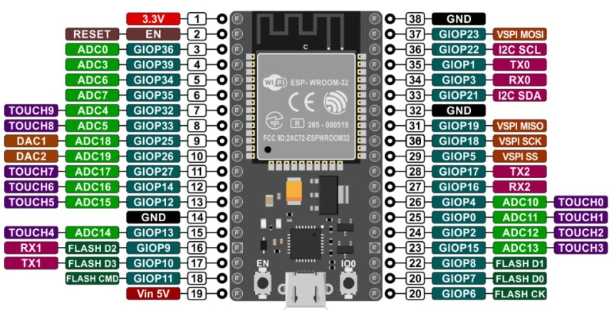
다음 링크를 참고해보니 GPIO 번호를 사용해보면 될듯하다.
https://blog.naver.com/mapes_khkim/221905932214
ESP32 사용하기(ARDUINO IDE)
ESP32 사용하기(ARDUINO IDE) ESP32 이란? ESP8266은 WIFI가 가능한 꽤 성능이 좋...
blog.naver.com
근데 ESP32 38핀 짜리 GPIO는 번호가 순서대로 가느네 아니라 뒤죽박죽 되있어서 좀햇갈리긴한다.
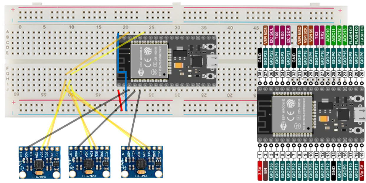
아쉬운데로 파워포인트로 대충 선 그렸는데
이런 느낌으로 배선하고
(mpu6050 vcc, gnd 제외)
이전 코드 참고해서 만들었는데
#include "I2Cdev.h"

#include "MPU6050_6Axis_MotionApps20.h"
#if I2CDEV_IMPLEMENTATION == I2CDEV_ARDUINO_WIRE
    #include "Wire.h"
#endif

// class default I2C address is 0x68
// specific I2C addresses may be passed as a parameter here
// AD0 low = 0x68 (default for SparkFun breakout and InvenSense evaluation board)
// AD0 high = 0x69
MPU6050 mpu;
//MPU6050 mpu(0x69); // <-- use for AD0 high

#define OUTPUT_READABLE_YAWPITCHROLL

// MPU control/status vars
bool dmpReady = false;  // set true if DMP init was successful
uint8_t mpuIntStatus;   // holds actual interrupt status byte from MPU
uint8_t devStatus;      // return status after each device operation (0 = success, !0 = error)
uint16_t packetSize;    // expected DMP packet size (default is 42 bytes)
uint16_t fifoCount;     // count of all bytes currently in FIFO
uint8_t fifoBuffer[64]; // FIFO storage buffer

// orientation/motion vars
Quaternion q;           // [w, x, y, z]         quaternion container
VectorInt16 aa;         // [x, y, z]            accel sensor measurements
VectorInt16 aaReal;     // [x, y, z]            gravity-free accel sensor measurements
VectorInt16 aaWorld;    // [x, y, z]            world-frame accel sensor measurements
VectorFloat gravity;    // [x, y, z]            gravity vector
float euler[3];         // [psi, theta, phi]    Euler angle container
float ypr[3];           // [yaw, pitch, roll]   yaw/pitch/roll container and gravity vector

volatile bool mpuInterrupt = false;     // indicates whether MPU interrupt pin has gone high
void dmpDataReady() {
    mpuInterrupt = true;
}


#include "BluetoothSerial.h"
String device_name = "ESP32-BT-Slave";

// Check if Bluetooth is available
#if !defined(CONFIG_BT_ENABLED) || !defined(CONFIG_BLUEDROID_ENABLED)
  #error Bluetooth is not enabled! Please run `make menuconfig` to and enable it
#endif

// Check Serial Port Profile
#if !defined(CONFIG_BT_SPP_ENABLED)
  #error Serial Port Profile for Bluetooth is not available or not enabled. It is only available for the ESP32 chip.
#endif

BluetoothSerial BTSerial;
int mpuPinNums[] = {36, 39, 34};
int mpuNum = sizeof(mpuPinNums) / sizeof(int);

void InitMPU(int pinNum);
void SendData(int pinNum);


void setup() {
  Serial.begin(115200);
  BTSerial.begin(device_name); //Bluetooth device name

  for (int i = 0; i < mpuNum;i++)
    pinMode(mpuPinNums[i], OUTPUT);

  // join I2C bus (I2Cdev library doesn't do this automatically)
  #if I2CDEV_IMPLEMENTATION == I2CDEV_ARDUINO_WIRE
      Wire.begin();
      Wire.setClock(400000); // 400kHz I2C clock. Comment this line if having compilation difficulties
  #elif I2CDEV_IMPLEMENTATION == I2CDEV_BUILTIN_FASTWIRE
      Fastwire::setup(400, true);
  #endif

  for (int i = 0; i < mpuNum;i++)
    InitMPU(mpuPinNums[i]);
}

void loop() {
  for (int i = 0; i < mpuNum;i++)
    SendData(mpuPinNums[i]);

  Serial.println("");


}


void InitMPU(int pinNum)
{
  for (int i = 0; i < mpuNum; i++)
  {
    if (mpuPinNums[i] == pinNum)
      digitalWrite(mpuPinNums[i], LOW);  //set selected mpu6050 addr 0x68
    else
      digitalWrite(mpuPinNums[i], HIGH);  //set other mpu6050 addr 0x69
  }
  Serial.print("start init pin ");
  Serial.println(pinNum);

  // initialize device
  mpu.initialize();

  // verify connection
  Serial.println(F("Testing device connections..."));
  Serial.println(mpu.testConnection() ? F("MPU6050 connection successful") : F("MPU6050 connection failed"));

  // load and configure the DMP
  Serial.println(F("Initializing DMP..."));
  devStatus = mpu.dmpInitialize();

  // supply your own gyro offsets here, scaled for min sensitivity
  mpu.setXGyroOffset(220);
  mpu.setYGyroOffset(76);
  mpu.setZGyroOffset(-85);
  mpu.setZAccelOffset(1788); // 1688 factory default for my test chip

  // make sure it worked (returns 0 if so)
  if (devStatus == 0) {
      // turn on the DMP, now that it's ready
      Serial.println(F("Enabling DMP..."));
      mpu.setDMPEnabled(true);

      // enable Arduino interrupt detection
      Serial.println(F("Enabling interrupt detection (Arduino external interrupt 0)..."));
      attachInterrupt(0, dmpDataReady, RISING);
      //attachInterrupt(digitalPinToInterrupt(INTERRUPT_PIN), dmpDataReady, RISING);

      mpuIntStatus = mpu.getIntStatus();

      // set our DMP Ready flag so the main loop() function knows it's okay to use it
      Serial.println(F("DMP ready! Waiting for first interrupt..."));
      dmpReady = true;

      // get expected DMP packet size for later comparison
      packetSize = mpu.dmpGetFIFOPacketSize();
  } else {
      Serial.print(F("DMP Initialization failed (code "));
      Serial.print(devStatus);
      Serial.println(F(")"));
  }
}


void SendData(int pinNum)
{
  for (int i = 0; i < mpuNum; i++)
  {
    if (mpuPinNums[i] == pinNum)
      digitalWrite(mpuPinNums[i], LOW);  //set selected mpu6050 addr 0x68
    else
      digitalWrite(mpuPinNums[i], HIGH);  //set other mpu6050 addr 0x69
  }

  // if programming failed, don't try to do anything
  if (!dmpReady) return;

  mpuIntStatus = mpu.getIntStatus();

  // get current FIFO count
  fifoCount = mpu.getFIFOCount();

  // check for overflow (this should never happen unless our code is too inefficient)
  if ((mpuIntStatus & 0x10) || fifoCount == 1024) {
      // reset so we can continue cleanly
      mpu.resetFIFO();
  // otherwise, check for DMP data ready interrupt (this should happen frequently)
  } else if (mpuIntStatus & 0x02) {
    // wait for correct available data length, should be a VERY short wait
    while (fifoCount < packetSize) fifoCount = mpu.getFIFOCount();

    // read a packet from FIFO
    mpu.getFIFOBytes(fifoBuffer, packetSize);

    // track FIFO count here in case there is > 1 packet available
    fifoCount -= packetSize;

    #ifdef OUTPUT_READABLE_YAWPITCHROLL
        // display Euler angles in degrees
        mpu.dmpGetQuaternion(&q, fifoBuffer);
        mpu.dmpGetGravity(&gravity, &q);
        mpu.dmpGetYawPitchRoll(ypr, &q, &gravity);
        Serial.print(pinNum);
        Serial.print(":");
        Serial.print(int(ypr[0] * 180/M_PI));
        Serial.print(",");
        Serial.print(int(ypr[1] * 180/M_PI));
        Serial.print(",");
        Serial.print(int(ypr[2] * 180/M_PI));
        Serial.print("/");
    #endif
  }
}
GPIO를 인풋모드로밖에 못쓴다면서
데이터가 가끔 조금 나왔다가 말고
제대로 안나온다.
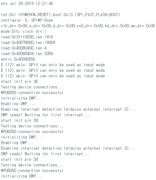
왜이런가 싶어 구글링해보니 이쪽 핀들은 인풋으로 밖에 못쓴다고하네

문제 고치고 시리얼로 출력해보면
#include "I2Cdev.h"

#include "MPU6050_6Axis_MotionApps20.h"
#if I2CDEV_IMPLEMENTATION == I2CDEV_ARDUINO_WIRE
    #include "Wire.h"
#endif

// class default I2C address is 0x68
// specific I2C addresses may be passed as a parameter here
// AD0 low = 0x68 (default for SparkFun breakout and InvenSense evaluation board)
// AD0 high = 0x69
MPU6050 mpu;
//MPU6050 mpu(0x69); // <-- use for AD0 high

#define OUTPUT_READABLE_YAWPITCHROLL

// MPU control/status vars
bool dmpReady = false;  // set true if DMP init was successful
uint8_t mpuIntStatus;   // holds actual interrupt status byte from MPU
uint8_t devStatus;      // return status after each device operation (0 = success, !0 = error)
uint16_t packetSize;    // expected DMP packet size (default is 42 bytes)
uint16_t fifoCount;     // count of all bytes currently in FIFO
uint8_t fifoBuffer[64]; // FIFO storage buffer

// orientation/motion vars
Quaternion q;           // [w, x, y, z]         quaternion container
VectorInt16 aa;         // [x, y, z]            accel sensor measurements
VectorInt16 aaReal;     // [x, y, z]            gravity-free accel sensor measurements
VectorInt16 aaWorld;    // [x, y, z]            world-frame accel sensor measurements
VectorFloat gravity;    // [x, y, z]            gravity vector
float euler[3];         // [psi, theta, phi]    Euler angle container
float ypr[3];           // [yaw, pitch, roll]   yaw/pitch/roll container and gravity vector

volatile bool mpuInterrupt = false;     // indicates whether MPU interrupt pin has gone high
void dmpDataReady() {
    mpuInterrupt = true;
}


#include "BluetoothSerial.h"
String device_name = "ESP32-BT-Slave";

// Check if Bluetooth is available
#if !defined(CONFIG_BT_ENABLED) || !defined(CONFIG_BLUEDROID_ENABLED)
  #error Bluetooth is not enabled! Please run `make menuconfig` to and enable it
#endif

// Check Serial Port Profile
#if !defined(CONFIG_BT_SPP_ENABLED)
  #error Serial Port Profile for Bluetooth is not available or not enabled. It is only available for the ESP32 chip.
#endif

BluetoothSerial BTSerial;
int mpuPinNums[] = {32, 33, 25};
int mpuNum = sizeof(mpuPinNums) / sizeof(int);

void InitMPU(int pinNum);
void SendData(int pinNum);


void setup() {
  Serial.begin(115200);
  BTSerial.begin(device_name); //Bluetooth device name

  Serial.print("start init mpuNum : ");
  Serial.println(mpuNum);

  for (int i = 0; i < mpuNum;i++)
  {
    Serial.print("set pin output : ");
    Serial.println(mpuPinNums[i]);
    pinMode(mpuPinNums[i], OUTPUT);

  }

  // join I2C bus (I2Cdev library doesn't do this automatically)
  #if I2CDEV_IMPLEMENTATION == I2CDEV_ARDUINO_WIRE
      Wire.begin();
      Wire.setClock(400000); // 400kHz I2C clock. Comment this line if having compilation difficulties
  #elif I2CDEV_IMPLEMENTATION == I2CDEV_BUILTIN_FASTWIRE
      Fastwire::setup(400, true);
  #endif

  for (int i = 0; i < mpuNum;i++)
    InitMPU(mpuPinNums[i]);
}

void loop() {
  for (int i = 0; i < mpuNum;i++)
    SendData(mpuPinNums[i]);

  Serial.println("");


}


void InitMPU(int pinNum)
{
  for (int i = 0; i < mpuNum; i++)
  {
    if (mpuPinNums[i] == pinNum)
      digitalWrite(mpuPinNums[i], LOW);  //set selected mpu6050 addr 0x68
    else
      digitalWrite(mpuPinNums[i], HIGH);  //set other mpu6050 addr 0x69
  }

  // initialize device
  mpu.initialize();

  // verify connection
  Serial.println(F("Testing device connections..."));
  Serial.println(mpu.testConnection() ? F("MPU6050 connection successful") : F("MPU6050 connection failed"));

  // load and configure the DMP
  Serial.println(F("Initializing DMP..."));
  devStatus = mpu.dmpInitialize();

  // supply your own gyro offsets here, scaled for min sensitivity
  mpu.setXGyroOffset(220);
  mpu.setYGyroOffset(76);
  mpu.setZGyroOffset(-85);
  mpu.setZAccelOffset(1788); // 1688 factory default for my test chip

  // make sure it worked (returns 0 if so)
  if (devStatus == 0) {
      // turn on the DMP, now that it's ready
      Serial.println(F("Enabling DMP..."));
      mpu.setDMPEnabled(true);

      // enable Arduino interrupt detection
      Serial.println(F("Enabling interrupt detection (Arduino external interrupt 0)..."));
      attachInterrupt(0, dmpDataReady, RISING);
      //attachInterrupt(digitalPinToInterrupt(INTERRUPT_PIN), dmpDataReady, RISING);

      mpuIntStatus = mpu.getIntStatus();

      // set our DMP Ready flag so the main loop() function knows it's okay to use it
      Serial.println(F("DMP ready! Waiting for first interrupt..."));
      dmpReady = true;

      // get expected DMP packet size for later comparison
      packetSize = mpu.dmpGetFIFOPacketSize();
  } else {
      Serial.print(F("DMP Initialization failed (code "));
      Serial.print(devStatus);
      Serial.println(F(")"));
  }
}


void SendData(int pinNum)
{
  for (int i = 0; i < mpuNum; i++)
  {
    if (mpuPinNums[i] == pinNum)
      digitalWrite(mpuPinNums[i], LOW);  //set selected mpu6050 addr 0x68
    else
      digitalWrite(mpuPinNums[i], HIGH);  //set other mpu6050 addr 0x69
  }

  // if programming failed, don't try to do anything
  if (!dmpReady) return;

  mpuIntStatus = mpu.getIntStatus();

  // get current FIFO count
  fifoCount = mpu.getFIFOCount();

  // check for overflow (this should never happen unless our code is too inefficient)
  if ((mpuIntStatus & 0x10) || fifoCount == 1024) {
      // reset so we can continue cleanly
      mpu.resetFIFO();
  // otherwise, check for DMP data ready interrupt (this should happen frequently)
  } else if (mpuIntStatus & 0x02) {
    // wait for correct available data length, should be a VERY short wait
    while (fifoCount < packetSize) fifoCount = mpu.getFIFOCount();

    // read a packet from FIFO
    mpu.getFIFOBytes(fifoBuffer, packetSize);

    // track FIFO count here in case there is > 1 packet available
    fifoCount -= packetSize;

    #ifdef OUTPUT_READABLE_YAWPITCHROLL
        // display Euler angles in degrees
        mpu.dmpGetQuaternion(&q, fifoBuffer);
        mpu.dmpGetGravity(&gravity, &q);
        mpu.dmpGetYawPitchRoll(ypr, &q, &gravity);
        Serial.print(pinNum);
        Serial.print(":");
        Serial.print(int(ypr[0] * 180/M_PI));
        Serial.print(",");
        Serial.print(int(ypr[1] * 180/M_PI));
        Serial.print(",");
        Serial.print(int(ypr[2] * 180/M_PI));
        Serial.print("/");
    #endif
  }
}
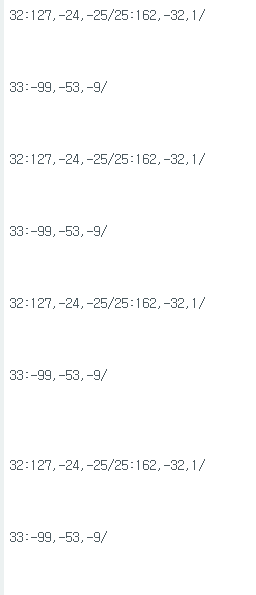
잘 나오기는한데 뭔가 좀 이상하다.
그냥 대충 전역 딕셔너리 이용해서 쓰고싶은데
구글링으로 esp32에서 map 사용하는 내용 찾았다.
이걸 쓰기전에 먼저 \n이 왜 자주발생하는지부터 찾아서 해결하고 넘어가야겠다.
https://techtutorialsx.com/2021/11/02/esp32-the-cpp-map-container/
ESP32: The C++ map container - techtutorialsx
How to execute some basic operations on a std::map container. We will be using the ESP32 and the Arduino
techtutorialsx.com
중간에 핀번호랑 인터럽트 상태 등 출력하도록 잠깐추가
  // get current FIFO count
  fifoCount = mpu.getFIFOCount();

  Serial.print(pinNum);
  Serial.print("pin dmpReady : ");
  Serial.print(", after mpuIntStatus : ");
  Serial.print(mpuIntStatus);
  Serial.print(", fifocount : ");
  Serial.println(fifoCount);

  // check for overflow (this should never happen unless our code is too inefficient)
  if ((mpuIntStatus & 0x10) || fifoCount == 1024) {
      // reset so we can continue cleanly
      mpu.resetFIFO();
지금은또 지저분하긴하지만 멀정하게 잘나오는듯하다.
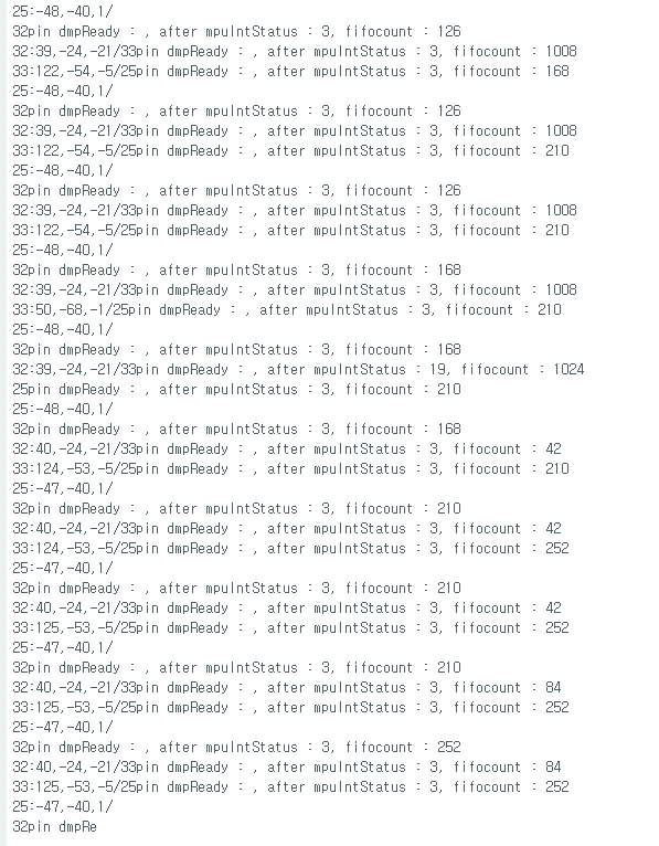
지우고봐도 값은 정상적인거같은데
왜이렇게 println이 많이 적용된건진 모르겟다.
이렇게 많이 시키진않았다만
대충 값은 잘들어오니 그냥 맵에 저장하도록 수정
map 사용하려고하는데 value 자리에 int[3]이 잘안된다.
아래 링크에서 배열 대신 구조체 쓰는내용을 봐서 수정
https://stackoverflow.com/questions/2582529/how-can-i-use-an-array-as-map-value
How can I use an array as map value?
I'm trying to create a map, where the key is an int, and the value is an array as follows: int red[3] = {1,0,0}; int green[3] = {0,1,0}; int blue[3] = {0,0,1}; std::map<int, int[3]> colou...
stackoverflow.com
struct YPR
{
    int ypr[3];
};
std::map<int, YPR> yprMap;


void InitMPU(int pinNum);
void SendData(int pinNum);

void setup() {
  Serial.begin(115200);
  BTSerial.begin(device_name); //Bluetooth device name

  YPR zeroYpr = {0, 0, 0};
  for(int i = 0; i < mpuNum; i++)
    yprMap.insert(std::pair<int,YPR>(mpuPinNums[i], zeroYpr));
블루투스로 보내도록 전체코드 정리
#include "I2Cdev.h"
#include <map>

#include "MPU6050_6Axis_MotionApps20.h"
#if I2CDEV_IMPLEMENTATION == I2CDEV_ARDUINO_WIRE
    #include "Wire.h"
#endif

MPU6050 mpu;

#define OUTPUT_READABLE_YAWPITCHROLL

// MPU control/status vars
bool dmpReady = false;  // set true if DMP init was successful
uint8_t mpuIntStatus;   // holds actual interrupt status byte from MPU
uint8_t devStatus;      // return status after each device operation (0 = success, !0 = error)
uint16_t packetSize;    // expected DMP packet size (default is 42 bytes)
uint16_t fifoCount;     // count of all bytes currently in FIFO
uint8_t fifoBuffer[64]; // FIFO storage buffer

// orientation/motion vars
Quaternion q;           // [w, x, y, z]         quaternion container
VectorInt16 aa;         // [x, y, z]            accel sensor measurements
VectorInt16 aaReal;     // [x, y, z]            gravity-free accel sensor measurements
VectorInt16 aaWorld;    // [x, y, z]            world-frame accel sensor measurements
VectorFloat gravity;    // [x, y, z]            gravity vector
float euler[3];         // [psi, theta, phi]    Euler angle container
float ypr[3];           // [yaw, pitch, roll]   yaw/pitch/roll container and gravity vector

volatile bool mpuInterrupt = false;     // indicates whether MPU interrupt pin has gone high
void dmpDataReady() {
    mpuInterrupt = true;
}


#include "BluetoothSerial.h"
String device_name = "ESP32-BT-Slave";

// Check if Bluetooth is available
#if !defined(CONFIG_BT_ENABLED) || !defined(CONFIG_BLUEDROID_ENABLED)
  #error Bluetooth is not enabled! Please run `make menuconfig` to and enable it
#endif

// Check Serial Port Profile
#if !defined(CONFIG_BT_SPP_ENABLED)
  #error Serial Port Profile for Bluetooth is not available or not enabled. It is only available for the ESP32 chip.
#endif

BluetoothSerial BTSerial;
int mpuPinNums[] = {32, 33, 25};
int mpuNum = sizeof(mpuPinNums) / sizeof(int);

struct YPR
{
    int ypr[3];
};
std::map<int, YPR> yprMap;


void InitMPU(int pinNum);
void GetData(int pinNum);
void SendData();

void setup() {
  //Serial.begin(115200);
  BTSerial.begin(device_name); //Bluetooth device name

  YPR zeroYpr = {0, 0, 0};
  for(int i = 0; i < mpuNum; i++)
    yprMap.insert(std::pair<int,YPR>(mpuPinNums[i], zeroYpr));

  BTSerial.print("start init mpuNum : ");
  BTSerial.println(mpuNum);

  for (int i = 0; i < mpuNum;i++)
  {
    BTSerial.print("set pin output : ");
    BTSerial.println(mpuPinNums[i]);
    pinMode(mpuPinNums[i], OUTPUT);

  }

  // join I2C bus (I2Cdev library doesn't do this automatically)
  #if I2CDEV_IMPLEMENTATION == I2CDEV_ARDUINO_WIRE
      Wire.begin();
      Wire.setClock(400000); // 400kHz I2C clock. Comment this line if having compilation difficulties
  #elif I2CDEV_IMPLEMENTATION == I2CDEV_BUILTIN_FASTWIRE
      Fastwire::setup(400, true);
  #endif

  for (int i = 0; i < mpuNum;i++)
    InitMPU(mpuPinNums[i]);
}

void loop() {
  for (int i = 0; i < mpuNum;i++)
    GetData(mpuPinNums[i]);

  SendData();
}


void InitMPU(int pinNum)
{
  for (int i = 0; i < mpuNum; i++)
  {
    if (mpuPinNums[i] == pinNum)
      digitalWrite(mpuPinNums[i], LOW);  //set selected mpu6050 addr 0x68
    else
      digitalWrite(mpuPinNums[i], HIGH);  //set other mpu6050 addr 0x69
  }

  // initialize device
  mpu.initialize();

  // verify connection
  BTSerial.println(F("Testing device connections..."));
  BTSerial.println(mpu.testConnection() ? F("MPU6050 connection successful") : F("MPU6050 connection failed"));

  // load and configure the DMP
  BTSerial.println(F("Initializing DMP..."));
  devStatus = mpu.dmpInitialize();

  // supply your own gyro offsets here, scaled for min sensitivity
  mpu.setXGyroOffset(220);
  mpu.setYGyroOffset(76);
  mpu.setZGyroOffset(-85);
  mpu.setZAccelOffset(1788); // 1688 factory default for my test chip

  // make sure it worked (returns 0 if so)
  if (devStatus == 0) {
      // turn on the DMP, now that it's ready
      BTSerial.println(F("Enabling DMP..."));
      mpu.setDMPEnabled(true);

      // enable Arduino interrupt detection
      BTSerial.println(F("Enabling interrupt detection (Arduino external interrupt 0)..."));
      attachInterrupt(0, dmpDataReady, RISING);
      //attachInterrupt(digitalPinToInterrupt(INTERRUPT_PIN), dmpDataReady, RISING);

      mpuIntStatus = mpu.getIntStatus();

      // set our DMP Ready flag so the main loop() function knows it's okay to use it
      BTSerial.println(F("DMP ready! Waiting for first interrupt..."));
      dmpReady = true;

      // get expected DMP packet size for later comparison
      packetSize = mpu.dmpGetFIFOPacketSize();
  } else {
      BTSerial.print(F("DMP Initialization failed (code "));
      BTSerial.print(devStatus);
      BTSerial.println(F(")"));
  }
}


void GetData(int pinNum)
{
  for (int i = 0; i < mpuNum; i++)
  {
    if (mpuPinNums[i] == pinNum)
      digitalWrite(mpuPinNums[i], LOW);  //set selected mpu6050 addr 0x68
    else
      digitalWrite(mpuPinNums[i], HIGH);  //set other mpu6050 addr 0x69
  }

  // if programming failed, don't try to do anything
  if (!dmpReady) return;

  mpuIntStatus = mpu.getIntStatus();

  // get current FIFO count
  fifoCount = mpu.getFIFOCount();

  // check for overflow (this should never happen unless our code is too inefficient)
  if ((mpuIntStatus & 0x10) || fifoCount == 1024) {
      // reset so we can continue cleanly
      mpu.resetFIFO();
  // otherwise, check for DMP data ready interrupt (this should happen frequently)
  } else if (mpuIntStatus & 0x02) {
    // wait for correct available data length, should be a VERY short wait
    while (fifoCount < packetSize) fifoCount = mpu.getFIFOCount();

    // read a packet from FIFO
    mpu.getFIFOBytes(fifoBuffer, packetSize);

    // track FIFO count here in case there is > 1 packet available
    fifoCount -= packetSize;

    #ifdef OUTPUT_READABLE_YAWPITCHROLL
      // display Euler angles in degrees
      mpu.dmpGetQuaternion(&q, fifoBuffer);
      mpu.dmpGetGravity(&gravity, &q);
      mpu.dmpGetYawPitchRoll(ypr, &q, &gravity);

      YPR tmpYpr;
      tmpYpr.ypr[0] = int(ypr[0] * 180/M_PI);
      tmpYpr.ypr[1] = int(ypr[1] * 180/M_PI);
      tmpYpr.ypr[2] = int(ypr[2] * 180/M_PI);

      yprMap[pinNum] = tmpYpr;
    #endif
  }
}


void SendData()
{
  for (int i = 0; i < mpuNum; i++)
  {
    BTSerial.print(mpuPinNums[i]);
    BTSerial.print(":");
    BTSerial.print(yprMap[mpuPinNums[i]].ypr[0]);
    BTSerial.print(",");
    BTSerial.print(yprMap[mpuPinNums[i]].ypr[1]);
    BTSerial.print(",");
    BTSerial.print(yprMap[mpuPinNums[i]].ypr[2]);
    if(i == mpuNum - 1)
      BTSerial.println("");
    else
      BTSerial.print("/");
  }
}
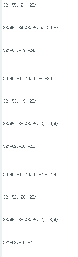
esp32 보조베터리 전원으로 mpu6050 ypr 송신하기
좌측 중간 오른쪽
32 33 25
순서인데
중간(초록불)에 있는 mpu6050은 이번에 알리에서 산게아닌 전에 있던거라 그런지
y 값이 혼자 다르다.
어쨋든 보조베터리 블루투스로 전체 데이터 빠르게 송신하니 됫지
'컴퓨터과학 > 언리얼' 카테고리의 다른 글
| 관성모션 - 16.관성센서 헛발질 (0) | 2024.03.12 |
|---|---|
| 관성모션 - 15. ESP32 MPU6050 여러 개 언리얼 액터 제어 (0) | 2024.03.02 |
| 관성모션 - 13. ESP32 블루투스 + MPU6050 YPR + 보조 베터리 (0) | 2024.02.28 |
| 관성모션 - 12. ESP32 블루투스 사용해보기 (0) | 2024.02.28 |
| 관성모션 - 11. MPU6050 여러 개 써보기(MUX 없이) + 인터럽트 상태 살펴보기 (0) | 2024.02.28 |