일단 이전 글에서 ESP32로 어떻게 블루투스 통신하는지는 살펴봤다.
이제 드뎌 MPU6050달아서 좀해보려고하는데
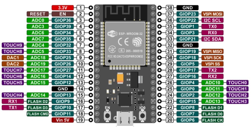
ESP32가 버전이 여러개있으면서 핀맵이 조금씩 다른것같다.
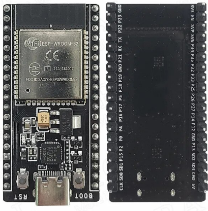
내가갖고있는건 아래거랑 비슷하지만 살짝다른데
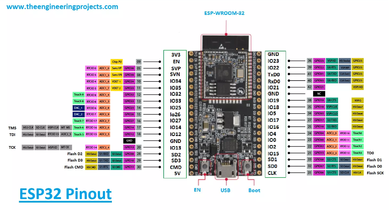
핀 내용이 뒷면에 있어서 빵판에 꽂으니 뭐가 뭔핀인지 모르겟다.
저사진 보고 따라가도 되나싶기도하고
구매한 사이트에서 확인하니 맞는것같다.
잠깐 찾아보니
이 글에서 esp32 gpio 설명을 잘 적어주긴했는데
30핀 기준인것같아 내꺼랑 맞는지는 좀봐야겟다.
https://mmirann.github.io/iot/arduino/2021/02/08/ESP32_GPIO.html
[ESP32] ESP32 GPIO PIN 별 사용법 | Miran Lee 👩💻
ESP 모듈은 블루투스, 와이파이를 기본적으로 사용할 수 있으며 36개의 GPIO가 사용 가능하다. 또한 별도로 보드 라이브러리를 설치하기만 하면 아두이노 IDE로 업로드가 가능하다. NodeMCU 보드는 이
mmirann.github.io
ESP32 30핀짜리 핀맵
ESP32 30핀짜리에는 GPIO21, GPIO22가 I2C 통신을 위해 사용되는데
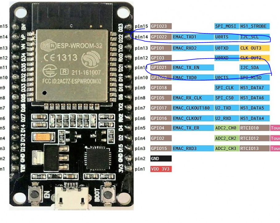
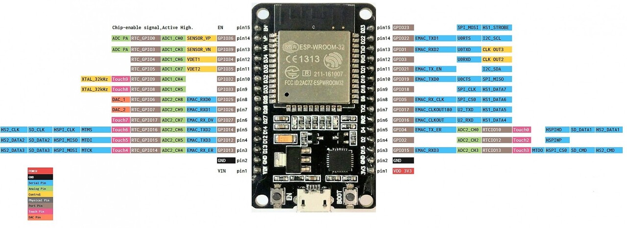
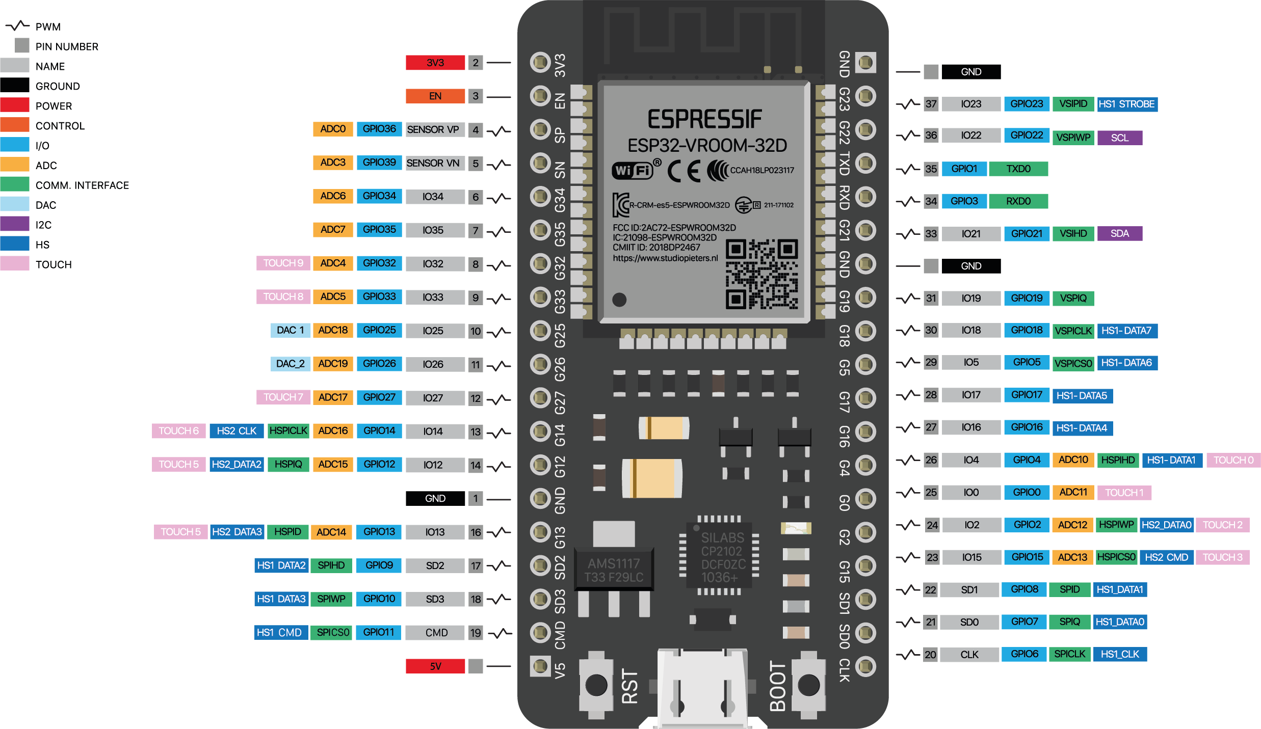
앞서 찾은 38핀 보드 핀아웃에는 i2c 핀 내용이 안보여서
다른 38핀 핀아웃도 찾아봄
GPIO 21, 22가 맞나부다.
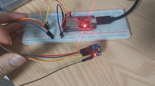
일단 위 핀맵 참고해서
I2C 통신할수 있도록 연결했다.
3V3은 빨간색
GND 파랑,어두운색
SCL 주황
SDA 노랑
esp32에서 mpu6050어떻게 쓸까 찾아보다가
찾은 글을 보니
내가 썻던 mpu6050 코드랑 거의 비슷해서 기존걸 사용하려햇는데
https://dev.to/shilleh/measure-angles-with-mpu6050-and-esp32-part-2-3d-animation-1cmm
Measure Angles with MPU6050 and ESP32 (Part 2): 3D Animation
Learn how to visualize the MPU6050 angle data from the i2cdevlib in the Arduino Framework using...
dev.to
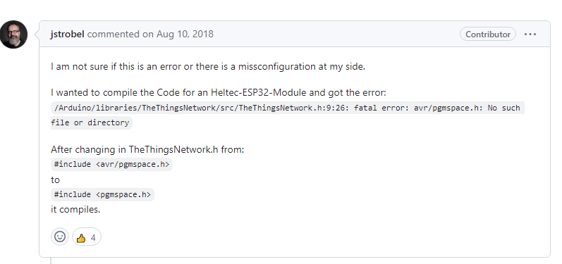
아두이노에서 사용할때랑 다르게
이 에러가 발생했다.
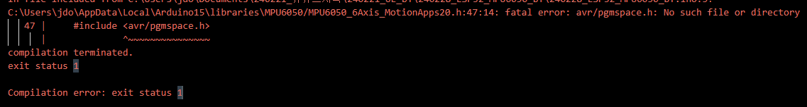
esp32는 avr이 아니니 뜨는게 당연하긴한데
구글링하니 어캐고치는지 찾음
그리고 아까 진행하다가
i2c 무슨 에러낫엇는데 캡처를 안하고 넘어가서 뭐엿는지 기억안난다.
여기서 시킨데로 i2cdev만 새로 다운받은걸로 교체
했더니 그냥 넘어가졋다.
[ESP32S]ESP32S 에서 MPU6050 사용시 에러 발생
해결: 하단부의 결론 부분에 정리를 하였다. 그 부분만 보면 된다. -------------------------------------...
blog.naver.com
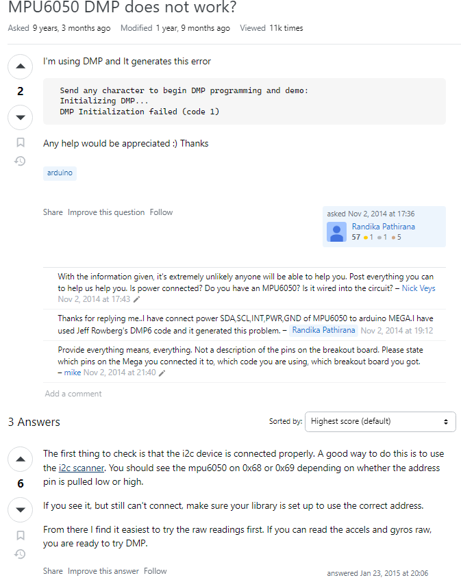
mpu6050 코드 업로드시키고 리셋했더니
자꾸 dmp 초기화 실패가 나온다.

원인 찾아보려고하는데
공급전압 문제라는 사람도있긴하지만
i2c scanner로 한번 스캐닝해보라는 글찾앗다.
대충 esp32 i2c scanner 찾아서 확인
https://wise-self.tistory.com/84
I2C Scanning on ESP32 using Arduino IDE
ESP32의 기본 I2C 핀은 다음과 같습니다. GPIO 22 (SCL), GPIO 21 (SDA) 이건 I2C 부품 주소 스캐닝 코드입니다. #include void setup() { Wire.begin(); Serial.begin(115200); Serial.println("\nI2C Scanner"); } void loop() { byte error, add
wise-self.tistory.com
i2c가 정상적으로 주소 찾긴했다.
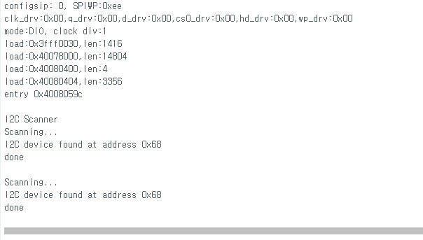
내가 뭘 실수했을까 다시보다보니
setup에서 i2c 초기화 부분을 제대로 안넣어뒀더라--
  // join I2C bus (I2Cdev library doesn't do this automatically)
  #if I2CDEV_IMPLEMENTATION == I2CDEV_ARDUINO_WIRE
      Wire.begin();
      Wire.setClock(400000); // 400kHz I2C clock. Comment this line if having compilation difficulties
  #elif I2CDEV_IMPLEMENTATION == I2CDEV_BUILTIN_FASTWIRE
      Fastwire::setup(400, true);
  #endif
다시 업로드하고 실행시켯는데
dmp 초기화는 잘된것같지만 자세 출력이 안된다..
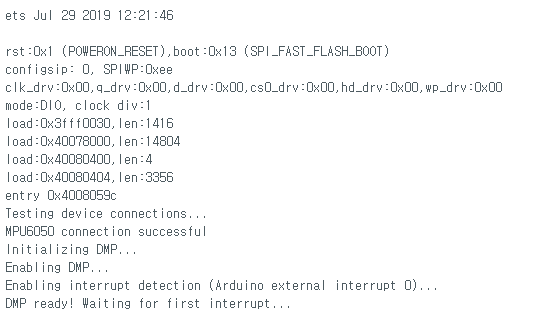
코드 중간에 mpu interrupt 기다리는 내용이 있어
여기서 막힌것으로 보인다.
  // wait for MPU interrupt or extra packet(s) available
  while (!mpuInterrupt && fifoCount < packetSize) {
  }

  // reset interrupt flag and get INT_STATUS byte
  mpuInterrupt = false;
이 부분을 지우고 나면 잘 동작
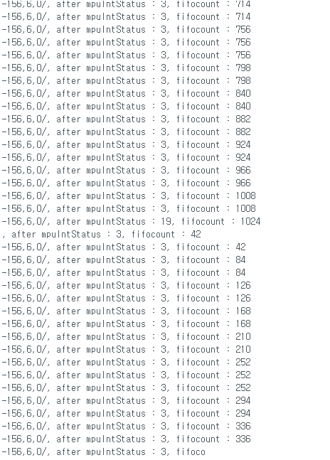
어짜피 인터럽트 안써도 대충 원하는대로 동작하므로
대충 FIFO가 가득차서 리프레시 할떄 뺴고는 잘나온다.
#include "I2Cdev.h"

#include "MPU6050_6Axis_MotionApps20.h"
#if I2CDEV_IMPLEMENTATION == I2CDEV_ARDUINO_WIRE
    #include "Wire.h"
#endif

// class default I2C address is 0x68
// specific I2C addresses may be passed as a parameter here
// AD0 low = 0x68 (default for SparkFun breakout and InvenSense evaluation board)
// AD0 high = 0x69
MPU6050 mpu;
//MPU6050 mpu(0x69); // <-- use for AD0 high

#define OUTPUT_READABLE_YAWPITCHROLL

// MPU control/status vars
bool dmpReady = false;  // set true if DMP init was successful
uint8_t mpuIntStatus;   // holds actual interrupt status byte from MPU
uint8_t devStatus;      // return status after each device operation (0 = success, !0 = error)
uint16_t packetSize;    // expected DMP packet size (default is 42 bytes)
uint16_t fifoCount;     // count of all bytes currently in FIFO
uint8_t fifoBuffer[64]; // FIFO storage buffer

// orientation/motion vars
Quaternion q;           // [w, x, y, z]         quaternion container
VectorInt16 aa;         // [x, y, z]            accel sensor measurements
VectorInt16 aaReal;     // [x, y, z]            gravity-free accel sensor measurements
VectorInt16 aaWorld;    // [x, y, z]            world-frame accel sensor measurements
VectorFloat gravity;    // [x, y, z]            gravity vector
float euler[3];         // [psi, theta, phi]    Euler angle container
float ypr[3];           // [yaw, pitch, roll]   yaw/pitch/roll container and gravity vector

// packet structure for InvenSense teapot demo
uint8_t teapotPacket[14] = { '$', 0x02, 0,0, 0,0, 0,0, 0,0, 0x00, 0x00, '\r', '\n' };


volatile bool mpuInterrupt = false;     // indicates whether MPU interrupt pin has gone high
void dmpDataReady() {
    mpuInterrupt = true;
}


#include "BluetoothSerial.h"

String device_name = "ESP32-BT-Slave";

// Check if Bluetooth is available
#if !defined(CONFIG_BT_ENABLED) || !defined(CONFIG_BLUEDROID_ENABLED)
  #error Bluetooth is not enabled! Please run `make menuconfig` to and enable it
#endif

// Check Serial Port Profile
#if !defined(CONFIG_BT_SPP_ENABLED)
  #error Serial Port Profile for Bluetooth is not available or not enabled. It is only available for the ESP32 chip.
#endif

BluetoothSerial BTSerial;

void setup() {
  // join I2C bus (I2Cdev library doesn't do this automatically)
  #if I2CDEV_IMPLEMENTATION == I2CDEV_ARDUINO_WIRE
      Wire.begin();
      Wire.setClock(400000); // 400kHz I2C clock. Comment this line if having compilation difficulties
  #elif I2CDEV_IMPLEMENTATION == I2CDEV_BUILTIN_FASTWIRE
      Fastwire::setup(400, true);
  #endif


  BTSerial.begin(device_name); //Bluetooth device name
  Serial.begin(115200);


  // initialize device
  mpu.initialize();

  // verify connection
  Serial.println(F("Testing device connections..."));
  Serial.println(mpu.testConnection() ? F("MPU6050 connection successful") : F("MPU6050 connection failed"));

  // load and configure the DMP
  Serial.println(F("Initializing DMP..."));
  devStatus = mpu.dmpInitialize();

  // supply your own gyro offsets here, scaled for min sensitivity
  mpu.setXGyroOffset(220);
  mpu.setYGyroOffset(76);
  mpu.setZGyroOffset(-85);
  mpu.setZAccelOffset(1788); // 1688 factory default for my test chip

  // make sure it worked (returns 0 if so)
  if (devStatus == 0) {
      // turn on the DMP, now that it's ready
      Serial.println(F("Enabling DMP..."));
      mpu.setDMPEnabled(true);

      // enable Arduino interrupt detection
      Serial.println(F("Enabling interrupt detection (Arduino external interrupt 0)..."));
      attachInterrupt(0, dmpDataReady, RISING);
      //attachInterrupt(digitalPinToInterrupt(INTERRUPT_PIN), dmpDataReady, RISING);

      mpuIntStatus = mpu.getIntStatus();

      // set our DMP Ready flag so the main loop() function knows it's okay to use it
      Serial.println(F("DMP ready! Waiting for first interrupt..."));
      dmpReady = true;

      // get expected DMP packet size for later comparison
      packetSize = mpu.dmpGetFIFOPacketSize();
  } else {
      Serial.print(F("DMP Initialization failed (code "));
      Serial.print(devStatus);
      Serial.println(F(")"));
  }


}

void loop() {


  // if programming failed, don't try to do anything
  if (!dmpReady) return;

  mpuIntStatus = mpu.getIntStatus();

  // get current FIFO count
  fifoCount = mpu.getFIFOCount();
  /*
  Serial.print(", after mpuIntStatus : ");
  Serial.print(mpuIntStatus);
  Serial.print(", fifocount : ");
  Serial.println(fifoCount);
  */
  // check for overflow (this should never happen unless our code is too inefficient)
  if ((mpuIntStatus & 0x10) || fifoCount == 1024) {
      // reset so we can continue cleanly
      mpu.resetFIFO();

  // otherwise, check for DMP data ready interrupt (this should happen frequently)
  } else if (mpuIntStatus & 0x02) {
    // wait for correct available data length, should be a VERY short wait
    while (fifoCount < packetSize) fifoCount = mpu.getFIFOCount();

    // read a packet from FIFO
    mpu.getFIFOBytes(fifoBuffer, packetSize);

    // track FIFO count here in case there is > 1 packet available
    // (this lets us immediately read more without waiting for an interrupt)
    fifoCount -= packetSize;

    #ifdef OUTPUT_READABLE_YAWPITCHROLL
        // display Euler angles in degrees
        mpu.dmpGetQuaternion(&q, fifoBuffer);
        mpu.dmpGetGravity(&gravity, &q);
        mpu.dmpGetYawPitchRoll(ypr, &q, &gravity);
        //Serial.print(pinNum);
        //Serial.print(":");
        Serial.print(int(ypr[0] * 180/M_PI));
        Serial.print(",");
        Serial.print(int(ypr[1] * 180/M_PI));
        Serial.print(",");
        Serial.print(int(ypr[2] * 180/M_PI));
        Serial.print("/");
    #endif
  }
  delay(20);
}
이제 블루투스로 넘어가서 동작시켜보자
위 코드를 블루투스 시리얼로 고친결과 잘 나온다.
문제는 보조베터리 상태에서도 잘되느냐

와 이제 보조베터리 전원으로도
블루투스 통해서 빠르게 ypr 값을 가져올수 있게됫다.

'컴퓨터과학 > 언리얼' 카테고리의 다른 글
| 관성모션 - 15. ESP32 MPU6050 여러 개 언리얼 액터 제어 (0) | 2024.03.02 |
|---|---|
| 관성모션 - 14. ESP32 MPU6050 여러 개 YPR 블루투스로 가져오기 (0) | 2024.02.29 |
| 관성모션 - 12. ESP32 블루투스 사용해보기 (0) | 2024.02.28 |
| 관성모션 - 11. MPU6050 여러 개 써보기(MUX 없이) + 인터럽트 상태 살펴보기 (0) | 2024.02.28 |
| 관성모션 - 10. MPU6050 두 개 써보기(I2C 멀티플렉서 없이) (0) | 2024.02.27 |