이전에 퀘스트2 virtual desktop인가 immersed인가 사용했었는데
거기서는 핸드 컨트롤러로 했었지만
컴퓨터에서는 손 자세 추정을 통해서 만들어 보려고 한다.
그런데 mediapipe의 손 랜드마크 추정을 쓰자니
그냥 파이썬처럼 쉽게 할수가 없다.
바젤 없이는 빌드는 물론 실행 조차 못한다하고

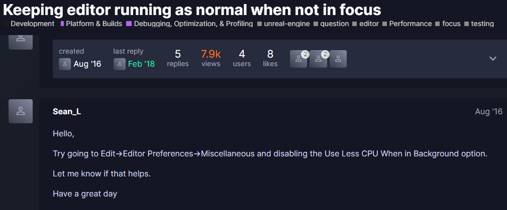
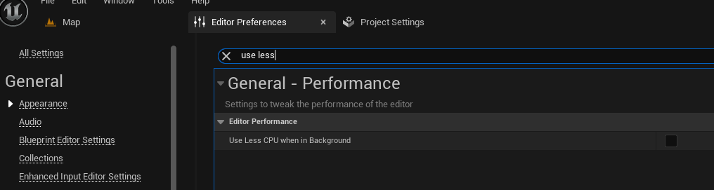
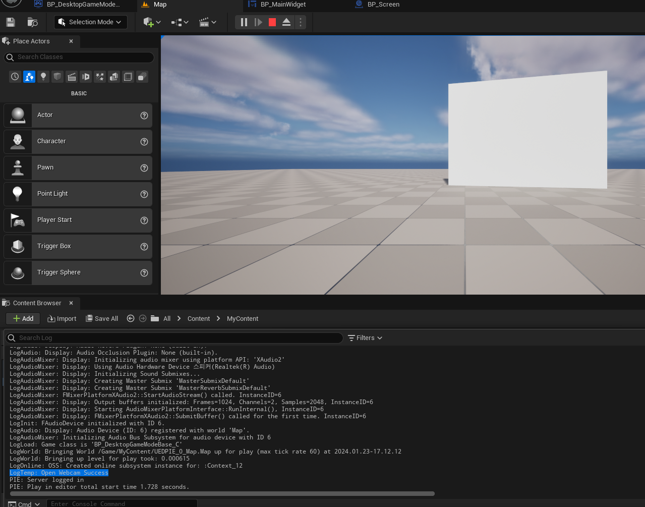
언리얼에선 파이썬 못쓰나 찾아봤지만
게임 실행중에는 안되고 에디터 상에서만 사용가능해보인다.
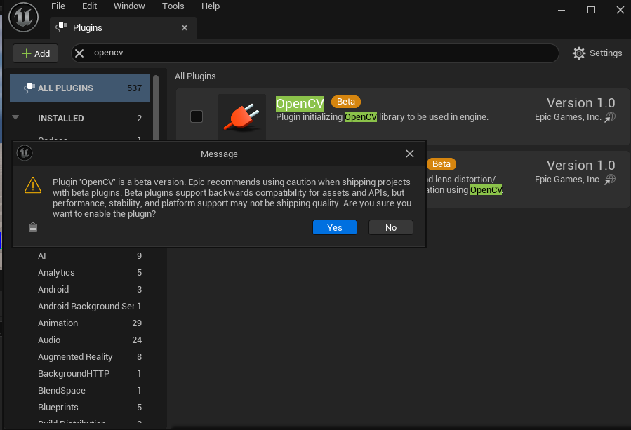
언리얼 미디어파이프 플러그인도 있긴한데 구버전에서 동작해서 잘 안되다보니
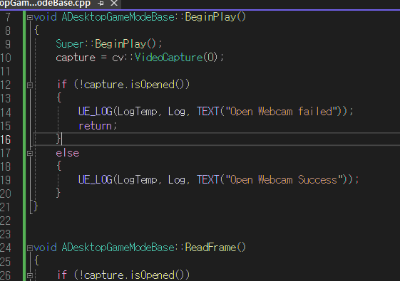
아쉬운데로 손 추정에 사용하는 모델을 cv::dnn 으로 추론해서
직접 사용해보려고한다.
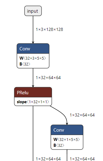
아래의 코드는 블라즈팜 오닉스 추론 예제인데
일단 파이썬으로 손 검출부터 해도 실제 손 전체를 못감싸준다.
여기서 사용한 블라즈팜이 128 x 128 입력으로받는 옛날 모델인데
미디어 파이프 모델들은 tflite로 올라와있지만 최근건 tflite2onnx로 변환이 불가
BlazePalm ONNX Inference Test
Colaboratory notebook
colab.research.google.com
전에는 못찾았는데
찾다보니 미디어파이프 tflite 모델을 파이토치 파일로 변환한걸 찾음
https://github.com/vidursatija/BlazePalm/blob/master/ML/ConverterPalmDetector.ipynb
https://github.com/zmurez/MediaPipePyTorch
GitHub - zmurez/MediaPipePyTorch: Port of MediaPipe tflite models to PyTorch
Port of MediaPipe tflite models to PyTorch. Contribute to zmurez/MediaPipePyTorch development by creating an account on GitHub.
github.com
다행이 이 링크에서 제공하는 데모에서는 미디어파이프 없이 blaze 핸드, 얼굴, 팜 등 코드가 동작한다.
여길 참고해서 c++에서 동작하게 고쳐주면 될듯한데
쉽진안지만 잘 모르는 pbtxt 범벅된 미디어파이프 코드보단 그래도 알아볼만하다.
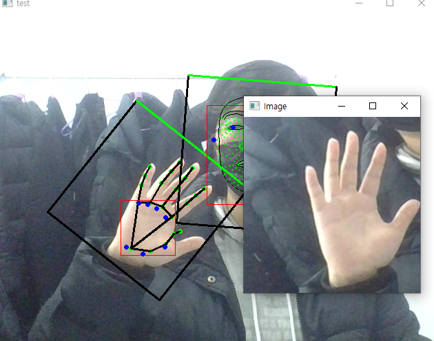
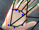
팜 디텍터 결과보면 손바닥 영역만 찾아내는게 맞앗었나보다.
그러면 블라즈 핸드의 입력으로 들어가는 이미지가 어떻게 되어있나 싶었는데
회전을 풀어낸 1 x 3 x 256 x 256 이미지였다.
블라즈 팜은 회전이 고려되지 않은 사각형이 나오는데
어떻게 손 방향대로 얼마만큼 회전된걸 알았길래 손을 위를 향하도록 되돌릴수 있었을까.
디텍션2roi 함수에서
xy 센터와 스케일, 세타(방향) 정보를 반환하도록 되어있다.

디텍션 2roi 보기전에 드로 디텍션을 봤다.
디텍션즈에 알고보니 뭔진 모를 키포인트 좌표도 같이 있었는데
손 내에 파란점들로
다시보니 손바닥 점들의 좌표를 나타내는 것으로 보인다.
아마 이 손바닥 키포인트들을 이용해서 방향을 찾은듯
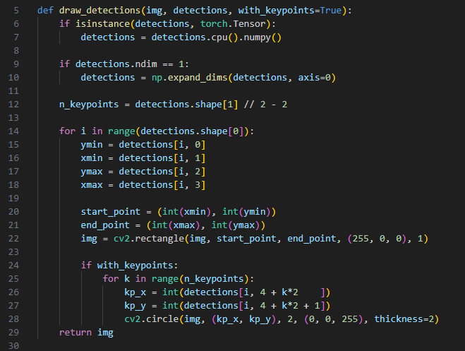
앞서 블라즈팜에서도 키포인트를 구해서 드로잉했던것처럼
디텍션2roi에선 이 블라즈팜 키포인트로 방향-세타 를 구해내도록 되어있다.
    def detection2roi(self, detection):
        """ Convert detections from detector to an oriented bounding box.

        Adapted from:
        # mediapipe/modules/face_landmark/face_detection_front_detection_to_roi.pbtxt

        The center and size of the box is calculated from the center
        of the detected box. Rotation is calcualted from the vector
        between kp1 and kp2 relative to theta0. The box is scaled
        and shifted by dscale and dy.

        """
        if self.detection2roi_method == 'box':
            # compute box center and scale
            # use mediapipe/calculators/util/detections_to_rects_calculator.cc
            xc = (detection[:,1] + detection[:,3]) / 2
            yc = (detection[:,0] + detection[:,2]) / 2
            scale = (detection[:,3] - detection[:,1]) # assumes square boxes

        elif self.detection2roi_method == 'alignment':
            # compute box center and scale
            # use mediapipe/calculators/util/alignment_points_to_rects_calculator.cc
            xc = detection[:,4+2*self.kp1]
            yc = detection[:,4+2*self.kp1+1]
            x1 = detection[:,4+2*self.kp2]
            y1 = detection[:,4+2*self.kp2+1]
            scale = ((xc-x1)**2 + (yc-y1)**2).sqrt() * 2
        else:
            raise NotImplementedError(
                "detection2roi_method [%s] not supported"%self.detection2roi_method)

        yc += self.dy * scale
        scale *= self.dscale

        # compute box rotation
        x0 = detection[:,4+2*self.kp1]
        y0 = detection[:,4+2*self.kp1+1]
        x1 = detection[:,4+2*self.kp2]
        y1 = detection[:,4+2*self.kp2+1]
        #theta = np.arctan2(y0-y1, x0-x1) - self.theta0
        theta = torch.atan2(y0-y1, x0-x1) - self.theta0
        return xc, yc, scale, theta
중심점과 세타는 그런데
스케일 계산에서 dscale이 뭔가 싶었는데
모델별로 기본 스케일 값이 있었다.

대충 궁금했던 내용은 여기까지보고
구현 흐름을 정리해보자.
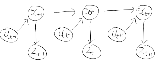
일단 아래 그림은 블라즈 핸드 동작 흐름 정리된 그림인데
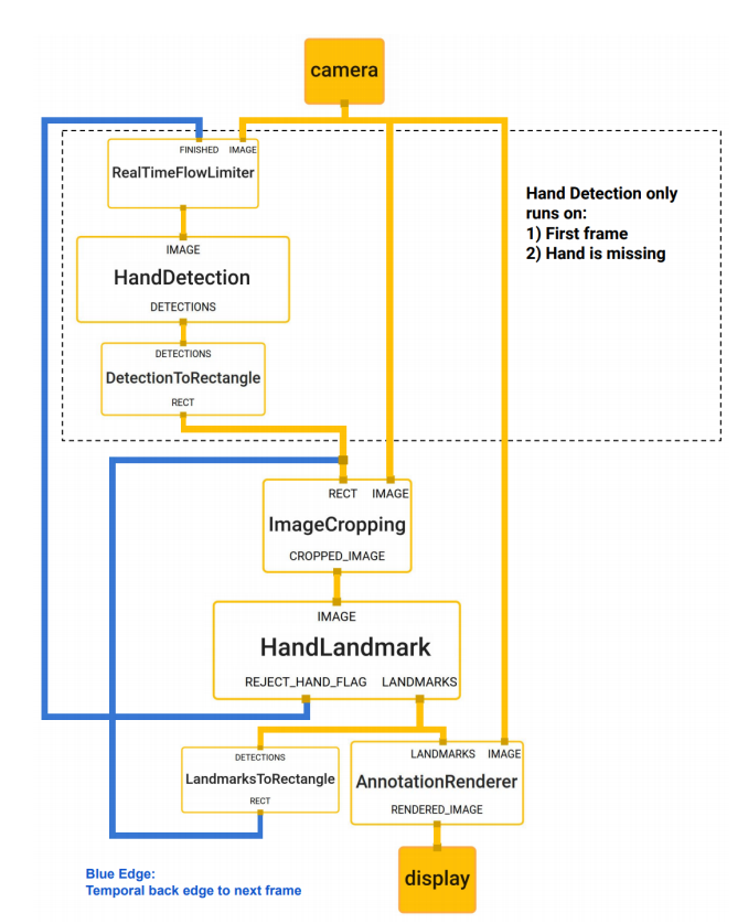
다시 코드보면서 정리해보자.
가장 먼저 이미지 가져온 후 리사이즈 패드 수행한다.
(중간에 다른 모델 코드는 제외)
if len(sys.argv) > 1:
    capture = cv2.VideoCapture(sys.argv[1])
    mirror_img = False
else:
    capture = cv2.VideoCapture(0)
    mirror_img = True

if capture.isOpened():
    hasFrame, frame = capture.read()
    frame_ct = 0
else:
    hasFrame = False

while hasFrame:
    frame_ct +=1

    if mirror_img:
        frame = np.ascontiguousarray(frame[:,::-1,::-1])
    else:
        frame = np.ascontiguousarray(frame[:,:,::-1])

    img1, img2, scale, pad = resize_pad(frame)
이 리사이즈 패드는
블라즈 모델들은 128 x 128, 256 x 256 크기 이미지를 사용해서
리사이징 + 패딩 처리 한뒤, 두 크기 이미지와 스케일과 패드 스케일을 반환한다.
def resize_pad(img):
    """ resize and pad images to be input to the detectors

    The face and palm detector networks take 256x256 and 128x128 images
    as input. As such the input image is padded and resized to fit the
    size while maintaing the aspect ratio.

    Returns:
        img1: 256x256
        img2: 128x128
        scale: scale factor between original image and 256x256 image
        pad: pixels of padding in the original image
    """

    size0 = img.shape
    if size0[0]>=size0[1]:
        h1 = 256
        w1 = 256 * size0[1] // size0[0]
        padh = 0
        padw = 256 - w1
        scale = size0[1] / w1
    else:
        h1 = 256 * size0[0] // size0[1]
        w1 = 256
        padh = 256 - h1
        padw = 0
        scale = size0[0] / h1
    padh1 = padh//2
    padh2 = padh//2 + padh%2
    padw1 = padw//2
    padw2 = padw//2 + padw%2
    img1 = cv2.resize(img, (w1,h1))
    img1 = np.pad(img1, ((padh1, padh2), (padw1, padw2), (0,0)))
    pad = (int(padh1 * scale), int(padw1 * scale))
    img2 = cv2.resize(img1, (128,128))
    return img1, img2, scale, pad
리사이즈 패드해서 얻은 이미지로
예측해서 정규화된 팜 디택션 결과들을 가져옴
    img1, img2, scale, pad = resize_pad(frame)

    normalized_palm_detections = palm_detector.predict_on_image(img1)
프레딕트 이미지를 보면
프레딕트 온 배치로 넘어가지는데
    def predict_on_image(self, img):
        """Makes a prediction on a single image.

        Arguments:
            img: a NumPy array of shape (H, W, 3) or a PyTorch tensor of
                 shape (3, H, W). The image's height and width should be
                 128 pixels.

        Returns:
            A tensor with face detections.
        """
        if isinstance(img, np.ndarray):
            img = torch.from_numpy(img).permute((2, 0, 1))

        return self.predict_on_batch(img.unsqueeze(0))[0]
중간에 전처리 -> 모델 추론 -> 후처리 -> 디텍션 획득 -> 비최대 억제 -> 필터링된 디텍션 반환
의 흐름으로 수행된다.
주석 내용을보니
디텍션은 0, 17 형태를 갖고있고
ymin, xmin, ymax, xmax, 키포인트xy 6개, 신뢰도 스코어 로 구성된다고 한다.
    def predict_on_batch(self, x):
        """Makes a prediction on a batch of images.

        Arguments:
            x: a NumPy array of shape (b, H, W, 3) or a PyTorch tensor of
               shape (b, 3, H, W). The height and width should be 128 pixels.

        Returns:
            A list containing a tensor of face detections for each image in
            the batch. If no faces are found for an image, returns a tensor
            of shape (0, 17).

        Each face detection is a PyTorch tensor consisting of 17 numbers:
            - ymin, xmin, ymax, xmax
            - x,y-coordinates for the 6 keypoints
            - confidence score
        """
        if isinstance(x, np.ndarray):
            x = torch.from_numpy(x).permute((0, 3, 1, 2))

        assert x.shape[1] == 3
        assert x.shape[2] == self.y_scale
        assert x.shape[3] == self.x_scale

        # 1. Preprocess the images into tensors:
        x = x.to(self._device())
        x = self._preprocess(x)

        # 2. Run the neural network:
        with torch.no_grad():
            out = self.__call__(x)

        # 3. Postprocess the raw predictions:
        detections = self._tensors_to_detections(out[0], out[1], self.anchors)

        # 4. Non-maximum suppression to remove overlapping detections:
        filtered_detections = []
        for i in range(len(detections)):
            faces = self._weighted_non_max_suppression(detections[i])
            faces = torch.stack(faces) if len(faces) > 0 else torch.zeros((0, self.num_coords+1))
            filtered_detections.append(faces)

        return filtered_detections
하지만 이렇게 얻은 팜 디텍션 결과는 정규화된 값으로
이전에 리사이즈 패드에서 얻은 스케일과 패드값으로 반정규화 시켜준다.
    normalized_palm_detections = palm_detector.predict_on_image(img1)

    palm_detections = denormalize_detections(normalized_palm_detections, scale, pad)
스케일과 패드를 이용해서 반정규화 코드는 이런식
def denormalize_detections(detections, scale, pad):
    """ maps detection coordinates from [0,1] to image coordinates

    The face and palm detector networks take 256x256 and 128x128 images
    as input. As such the input image is padded and resized to fit the
    size while maintaing the aspect ratio. This function maps the
    normalized coordinates back to the original image coordinates.

    Inputs:
        detections: nxm tensor. n is the number of detections.
            m is 4+2*k where the first 4 valuse are the bounding
            box coordinates and k is the number of additional
            keypoints output by the detector.
        scale: scalar that was used to resize the image
        pad: padding in the x and y dimensions

    """
    detections[:, 0] = detections[:, 0] * scale * 256 - pad[0]
    detections[:, 1] = detections[:, 1] * scale * 256 - pad[1]
    detections[:, 2] = detections[:, 2] * scale * 256 - pad[0]
    detections[:, 3] = detections[:, 3] * scale * 256 - pad[1]

    detections[:, 4::2] = detections[:, 4::2] * scale * 256 - pad[1]
    detections[:, 5::2] = detections[:, 5::2] * scale * 256 - pad[0]
    return detections
반정규화 이후에는 디텍션을 roi로 바꾸는데, (아까본거) xy 센터점과 스케일, 방향을 얻어내고
extract_roi로 원본 이미지로부터 img, affine2, box2를 가져오는데
    palm_detections = denormalize_detections(normalized_palm_detections, scale, pad)


    xc, yc, scale, theta = palm_detector.detection2roi(palm_detections.cpu())
    img, affine2, box2 = hand_regressor.extract_roi(frame, xc, yc, theta, scale)
roi 추출 코드를 보면
img는 정규화된 N x C x W x H 형태의 탠서이고
affines는 기울어진손 -> 정방향 손 어파인 변환을 위한, 역 어파인 변환 행렬
points는 어파인 변환에 사용하던 점들로 보인다.
    def extract_roi(self, frame, xc, yc, theta, scale):

        # take points on unit square and transform them according to the roi
        points = torch.tensor([[-1, -1, 1, 1],
                            [-1, 1, -1, 1]], device=scale.device).view(1,2,4)
        points = points * scale.view(-1,1,1)/2
        theta = theta.view(-1, 1, 1)
        R = torch.cat((
            torch.cat((torch.cos(theta), -torch.sin(theta)), 2),
            torch.cat((torch.sin(theta), torch.cos(theta)), 2),
            ), 1)
        center = torch.cat((xc.view(-1,1,1), yc.view(-1,1,1)), 1)
        points = R @ points + center

        # use the points to compute the affine transform that maps
        # these points back to the output square
        res = self.resolution
        points1 = np.array([[0, 0, res-1],
                            [0, res-1, 0]], dtype=np.float32).T
        affines = []
        imgs = []
        for i in range(points.shape[0]):
            pts = points[i, :, :3].cpu().numpy().T
            M = cv2.getAffineTransform(pts, points1)
            img = cv2.warpAffine(frame, M, (res,res))#, borderValue=127.5)
            img = torch.tensor(img, device=scale.device)
            imgs.append(img)
            affine = cv2.invertAffineTransform(M).astype('float32')
            affine = torch.tensor(affine, device=scale.device)
            affines.append(affine)
        if imgs:
            imgs = torch.stack(imgs).permute(0,3,1,2).float() / 255.#/ 127.5 - 1.0
            affines = torch.stack(affines)
        else:
            imgs = torch.zeros((0, 3, res, res), device=scale.device)
            affines = torch.zeros((0, 2, 3), device=scale.device)

        return imgs, affines, points
이렇게 구한 텐서(블롭) img를
hand_regressor(랜드마크 추정기)에 넣어서 플래그, 핸드, 정규화된 랜드마크들을 받아내느데
    flags2, handed2, normalized_landmarks2 = hand_regressor(img.to(gpu))
    landmarks2 = hand_regressor.denormalize_landmarks(normalized_landmarks2.cpu(), affine2)
핸드 랜드마크 추론 코드
    def forward(self, x):
        if x.shape[0] == 0:
            return torch.zeros((0,)), torch.zeros((0,)), torch.zeros((0, 21, 3))

        x = F.pad(x, (0, 1, 0, 1), "constant", 0)

        x = self.backbone1(x)
        y = self.backbone2(x)
        z = self.backbone3(y)
        w = self.backbone4(z)

        z = z + F.interpolate(w, scale_factor=2, mode='bilinear')
        z = self.blaze5(z)

        y = y + F.interpolate(z, scale_factor=2, mode='bilinear')
        y = self.blaze6(y)
        y = self.conv7(y)

        x = x + F.interpolate(y, scale_factor=2, mode='bilinear')

        x = self.backbone8(x)

        hand_flag = self.hand_flag(x).view(-1).sigmoid()
        handed = self.handed(x).view(-1).sigmoid()
        landmarks = self.landmarks(x).view(-1, 21, 3) / 256

        return hand_flag, handed, landmarks
마지막으로 랜드마크 반정규화를보면
랜드마크를 어파인 역변환 행렬과 곱하는 내용
여기서 나오는 래졸루션은 블라즈 핸드에 입력으로 사용하는 256
    def denormalize_landmarks(self, landmarks, affines):
        landmarks[:,:,:2] *= self.resolution
        for i in range(len(landmarks)):
            landmark, affine = landmarks[i], affines[i]
            landmark = (affine[:,:2] @ landmark[:,:2].T + affine[:,2:]).T
            landmarks[i,:,:2] = landmark
        return landmarks
class BlazeHandLandmark(BlazeLandmark):
    """The hand landmark model from MediaPipe.

    """
    def __init__(self):
        super(BlazeHandLandmark, self).__init__()

        # size of ROIs used for input
        self.resolution = 256
일단 여기까지 파이썬 코드 살펴봤으면
c++로 만들어볼수 있을듯
'컴퓨터과학 > 언리얼' 카테고리의 다른 글
| HandDesktop07 - blaze hand 사용 준비하기 (0) | 2024.01.26 |
|---|---|
| HandDesktop06 - blaze palm 사용하기 (0) | 2024.01.25 |
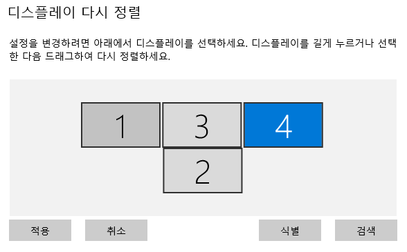
| HandDesktop04 - 다중 모니터 구현하기 (0) | 2024.01.24 |
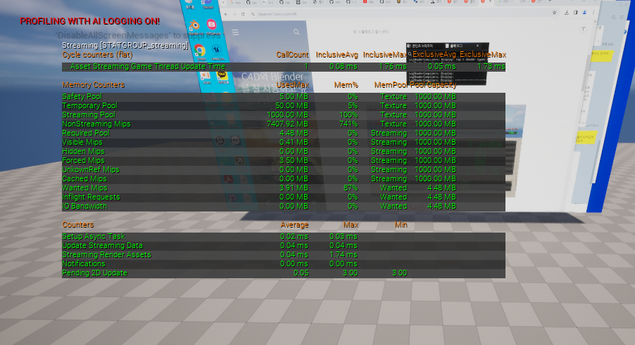
| HandDesktop03 - 다중 모니터 준비하기, 스트리밍 풀 문제 해결 (0) | 2024.01.24 |
| HandDesktop02 - 언리얼에 윈도우 화면 띄우기 (0) | 2024.01.23 |