// I2C device class (I2Cdev) demonstration Arduino sketch for MPU6050 class using DMP (MotionApps v2.0)// 6/21/2012 by Jeff Rowberg <jeff@rowberg.net>// Updates should (hopefully) always be available at https://github.com/jrowberg/i2cdevlib//// Changelog:// 2013-05-08 - added seamless Fastwire support// - added note about gyro calibration// 2012-06-21 - added note about Arduino 1.0.1 + Leonardo compatibility error// 2012-06-20 - improved FIFO overflow handling and simplified read process// 2012-06-19 - completely rearranged DMP initialization code and simplification// 2012-06-13 - pull gyro and accel data from FIFO packet instead of reading directly// 2012-06-09 - fix broken FIFO read sequence and change interrupt detection to RISING// 2012-06-05 - add gravity-compensated initial reference frame acceleration output// - add 3D math helper file to DMP6 example sketch// - add Euler output and Yaw/Pitch/Roll output formats// 2012-06-04 - remove accel offset clearing for better results (thanks Sungon Lee)// 2012-06-01 - fixed gyro sensitivity to be 2000 deg/sec instead of 250// 2012-05-30 - basic DMP initialization working/* ============================================
최신 코드
체인지로그
// I2C device class (I2Cdev) demonstration Arduino sketch for MPU6050 class using DMP (MotionApps v6.12)// 6/21/2012 by Jeff Rowberg <jeff@rowberg.net>// Updates should (hopefully) always be available at https://github.com/jrowberg/i2cdevlib//// Changelog:// 2019-07-10 - Uses the new version of the DMP Firmware V6.12// - Note: I believe the Teapot demo is broken with this versin as// - the fifo buffer structure has changed// 2016-04-18 - Eliminated a potential infinite loop// 2013-05-08 - added seamless Fastwire support// - added note about gyro calibration// 2012-06-21 - added note about Arduino 1.0.1 + Leonardo compatibility error// 2012-06-20 - improved FIFO overflow handling and simplified read process// 2012-06-19 - completely rearranged DMP initialization code and simplification// 2012-06-13 - pull gyro and accel data from FIFO packet instead of reading directly// 2012-06-09 - fix broken FIFO read sequence and change interrupt detection to RISING// 2012-06-05 - add gravity-compensated initial reference frame acceleration output// - add 3D math helper file to DMP6 example sketch// - add Euler output and Yaw/Pitch/Roll output formats// 2012-06-04 - remove accel offset clearing for better results (thanks Sungon Lee)// 2012-06-01 - fixed gyro sensitivity to be 2000 deg/sec instead of 250// 2012-05-30 - basic DMP initialization working/* ============================================
// I2C device class (I2Cdev) demonstration Arduino sketch for MPU6050 class using DMP (MotionApps v6.12)// 6/21/2012 by Jeff Rowberg <jeff@rowberg.net>// Updates should (hopefully) always be available at https://github.com/jrowberg/i2cdevlib//// Changelog:// 2019-07-10 - Uses the new version of the DMP Firmware V6.12// - Note: I believe the Teapot demo is broken with this versin as// - the fifo buffer structure has changed
#include"I2Cdev.h"#include<map>#include"MPU6050_6Axis_MotionApps20.h"#if I2CDEV_IMPLEMENTATION == I2CDEV_ARDUINO_WIRE#include"Wire.h"#endif
MPU6050 mpu;
#define OUTPUT_READABLE_YAWPITCHROLL// MPU control/status varsbool dmpReady = false; // set true if DMP init was successfuluint8_t mpuIntStatus; // holds actual interrupt status byte from MPUuint8_t devStatus; // return status after each device operation (0 = success, !0 = error)uint16_t packetSize; // expected DMP packet size (default is 42 bytes)uint16_t fifoCount; // count of all bytes currently in FIFOuint8_t fifoBuffer[64]; // FIFO storage buffer// orientation/motion vars
Quaternion q; // [w, x, y, z] quaternion container
VectorInt16 aa; // [x, y, z] accel sensor measurements
VectorInt16 aaReal; // [x, y, z] gravity-free accel sensor measurements
VectorInt16 aaWorld; // [x, y, z] world-frame accel sensor measurements
VectorFloat gravity; // [x, y, z] gravity vectorfloat euler[3]; // [psi, theta, phi] Euler angle containerfloat ypr[3]; // [yaw, pitch, roll] yaw/pitch/roll container and gravity vectorvolatilebool mpuInterrupt = false; // indicates whether MPU interrupt pin has gone highvoiddmpDataReady(){
mpuInterrupt = true;
}
#include"BluetoothSerial.h"
String device_name = "ESP32-BT-Slave";
// Check if Bluetooth is available#if !defined(CONFIG_BT_ENABLED) || !defined(CONFIG_BLUEDROID_ENABLED)#error Bluetooth is not enabled! Please run `make menuconfig` to and enable it#endif// Check Serial Port Profile#if !defined(CONFIG_BT_SPP_ENABLED)#error Serial Port Profile for Bluetooth is not available or not enabled. It is only available for the ESP32 chip.#endif
BluetoothSerial BTSerial;
int mpuPinNums[] = {32, 33, 25};
int mpuNum = sizeof(mpuPinNums) / sizeof(int);
structYPR
{int ypr[3];
};
std::map<int, YPR> yprMap;
voidInitMPU(int pinNum);
voidGetData(int pinNum);
voidSendData();
voidsetup(){
//Serial.begin(115200);
BTSerial.begin(device_name); //Bluetooth device name
YPR zeroYpr = {0, 0, 0};
for(int i = 0; i < mpuNum; i++)
yprMap.insert(std::pair<int,YPR>(mpuPinNums[i], zeroYpr));
BTSerial.print("start init mpuNum : ");
BTSerial.println(mpuNum);
for (int i = 0; i < mpuNum;i++)
{
BTSerial.print("set pin output : ");
BTSerial.println(mpuPinNums[i]);
pinMode(mpuPinNums[i], OUTPUT);
}
// join I2C bus (I2Cdev library doesn't do this automatically)#if I2CDEV_IMPLEMENTATION == I2CDEV_ARDUINO_WIRE
Wire.begin();
Wire.setClock(400000); // 400kHz I2C clock. Comment this line if having compilation difficulties#elif I2CDEV_IMPLEMENTATION == I2CDEV_BUILTIN_FASTWIRE
Fastwire::setup(400, true);
#endiffor (int i = 0; i < mpuNum;i++)
InitMPU(mpuPinNums[i]);
}
voidloop(){
for (int i = 0; i < mpuNum;i++)
GetData(mpuPinNums[i]);
SendData();
}
voidInitMPU(int pinNum){
for (int i = 0; i < mpuNum; i++)
{
if (mpuPinNums[i] == pinNum)
digitalWrite(mpuPinNums[i], LOW); //set selected mpu6050 addr 0x68elsedigitalWrite(mpuPinNums[i], HIGH); //set other mpu6050 addr 0x69
}
// initialize device
mpu.initialize();
// verify connection
BTSerial.println(F("Testing device connections..."));
BTSerial.println(mpu.testConnection() ? F("MPU6050 connection successful") : F("MPU6050 connection failed"));
// load and configure the DMP
BTSerial.println(F("Initializing DMP..."));
devStatus = mpu.dmpInitialize();
// supply your own gyro offsets here, scaled for min sensitivity
mpu.setXGyroOffset(220);
mpu.setYGyroOffset(76);
mpu.setZGyroOffset(-85);
mpu.setZAccelOffset(1788); // 1688 factory default for my test chip// make sure it worked (returns 0 if so)if (devStatus == 0) {
// turn on the DMP, now that it's ready
BTSerial.println(F("Enabling DMP..."));
mpu.setDMPEnabled(true);
// enable Arduino interrupt detection
BTSerial.println(F("Enabling interrupt detection (Arduino external interrupt 0)..."));
attachInterrupt(0, dmpDataReady, RISING);
//attachInterrupt(digitalPinToInterrupt(INTERRUPT_PIN), dmpDataReady, RISING);
mpuIntStatus = mpu.getIntStatus();
// set our DMP Ready flag so the main loop() function knows it's okay to use it
BTSerial.println(F("DMP ready! Waiting for first interrupt..."));
dmpReady = true;
// get expected DMP packet size for later comparison
packetSize = mpu.dmpGetFIFOPacketSize();
} else {
BTSerial.print(F("DMP Initialization failed (code "));
BTSerial.print(devStatus);
BTSerial.println(F(")"));
}
}
voidGetData(int pinNum){
for (int i = 0; i < mpuNum; i++)
{
if (mpuPinNums[i] == pinNum)
digitalWrite(mpuPinNums[i], LOW); //set selected mpu6050 addr 0x68elsedigitalWrite(mpuPinNums[i], HIGH); //set other mpu6050 addr 0x69
}
// if programming failed, don't try to do anythingif (!dmpReady) return;
mpuIntStatus = mpu.getIntStatus();
// get current FIFO count
fifoCount = mpu.getFIFOCount();
// check for overflow (this should never happen unless our code is too inefficient)if ((mpuIntStatus & 0x10) || fifoCount == 1024) {
// reset so we can continue cleanly
mpu.resetFIFO();
// otherwise, check for DMP data ready interrupt (this should happen frequently)
} elseif (mpuIntStatus & 0x02) {
// wait for correct available data length, should be a VERY short waitwhile (fifoCount < packetSize) fifoCount = mpu.getFIFOCount();
// read a packet from FIFO
mpu.getFIFOBytes(fifoBuffer, packetSize);
// track FIFO count here in case there is > 1 packet available
fifoCount -= packetSize;
#ifdef OUTPUT_READABLE_YAWPITCHROLL// display Euler angles in degrees
mpu.dmpGetQuaternion(&q, fifoBuffer);
mpu.dmpGetGravity(&gravity, &q);
mpu.dmpGetYawPitchRoll(ypr, &q, &gravity);
YPR tmpYpr;
tmpYpr.ypr[0] = int(ypr[0] * 180/M_PI);
tmpYpr.ypr[1] = int(ypr[1] * 180/M_PI);
tmpYpr.ypr[2] = int(ypr[2] * 180/M_PI);
yprMap[pinNum] = tmpYpr;
#endif
}
}
voidSendData(){
for (int i = 0; i < mpuNum; i++)
{
BTSerial.print(yprMap[mpuPinNums[i]].ypr[0]);
BTSerial.print(",");
BTSerial.print(yprMap[mpuPinNums[i]].ypr[1]);
BTSerial.print(",");
BTSerial.print(yprMap[mpuPinNums[i]].ypr[2]);
if(i == mpuNum - 1)
BTSerial.print("/");
else
BTSerial.print(":");
}
}
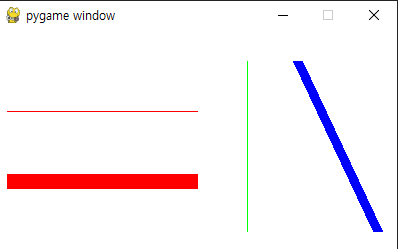
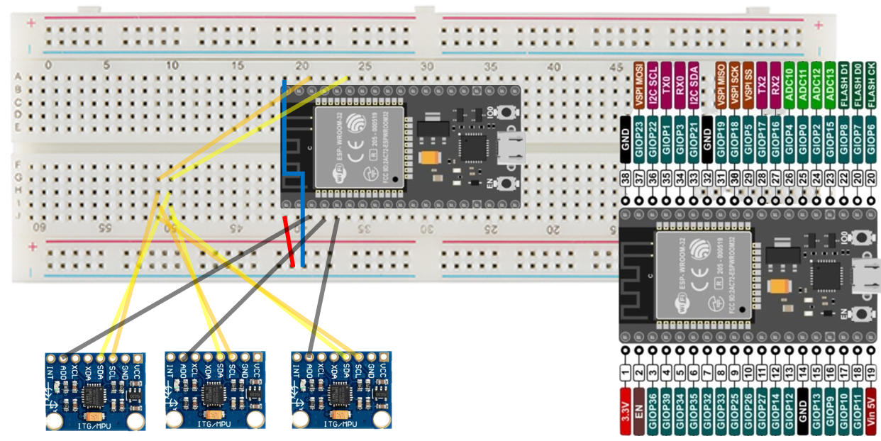
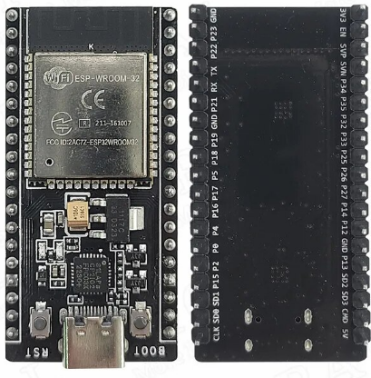
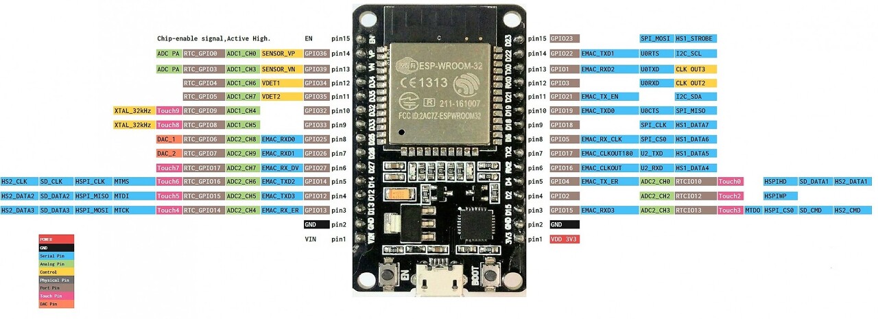
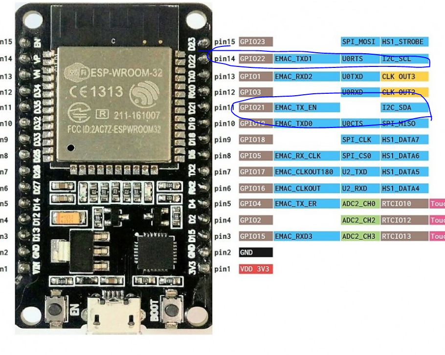
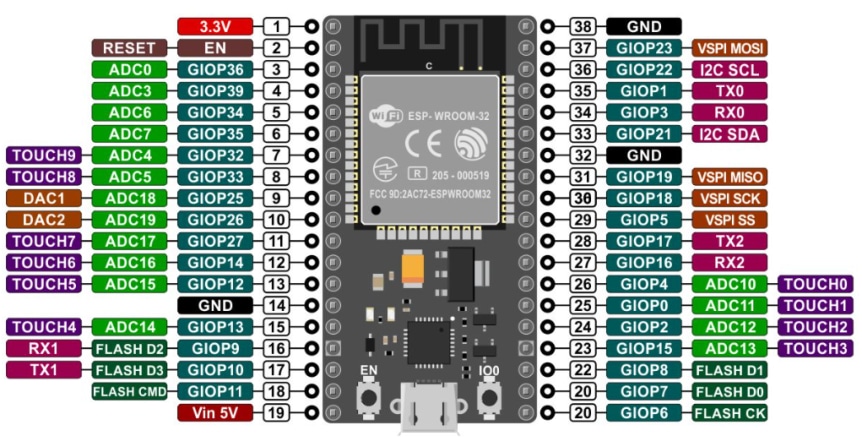
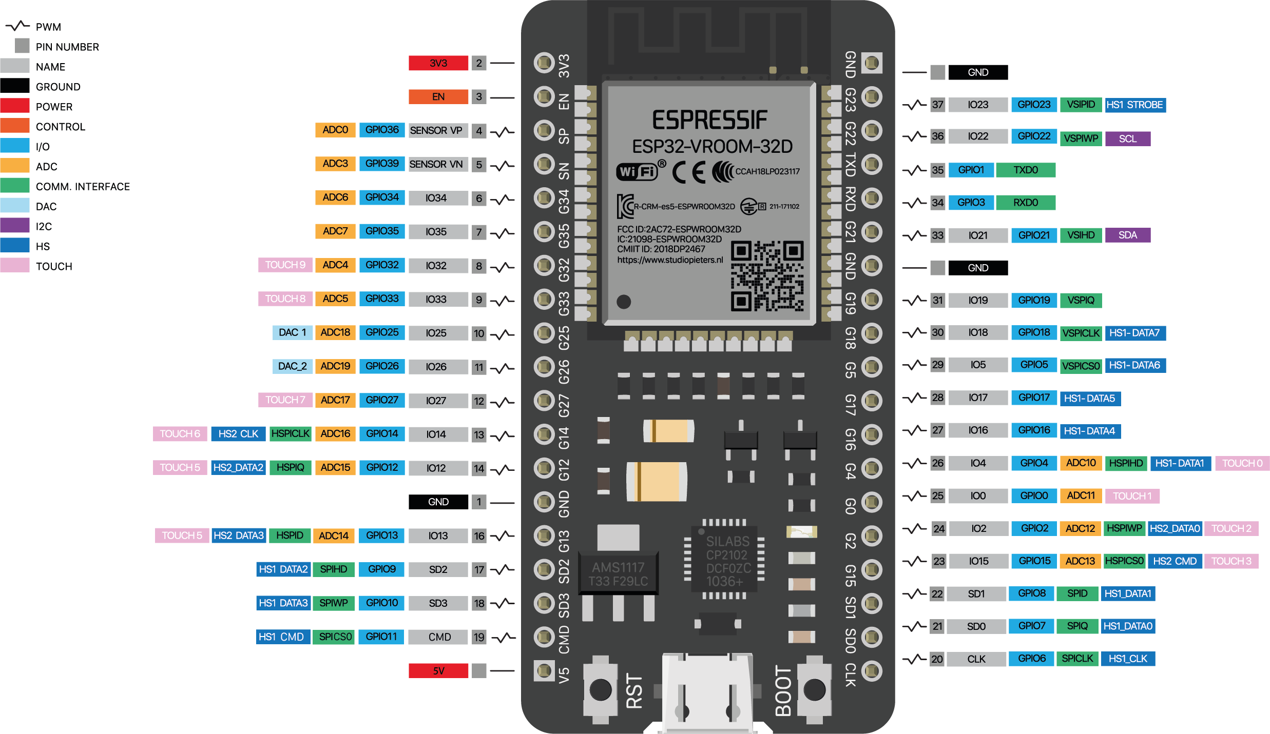
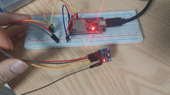
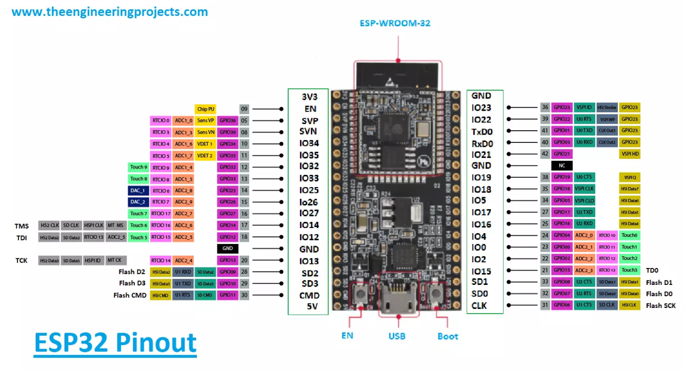
근데 ESP32 38핀 짜리 GPIO는 번호가 순서대로 가느네 아니라 뒤죽박죽 되있어서 좀햇갈리긴한다.
아쉬운데로 파워포인트로 대충 선 그렸는데
이런 느낌으로 배선하고
(mpu6050 vcc, gnd 제외)
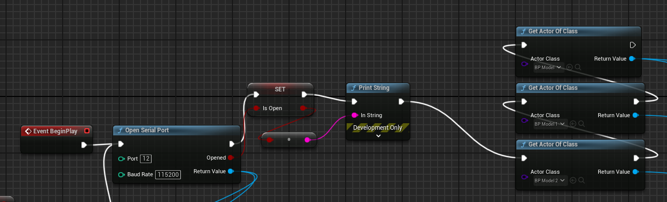
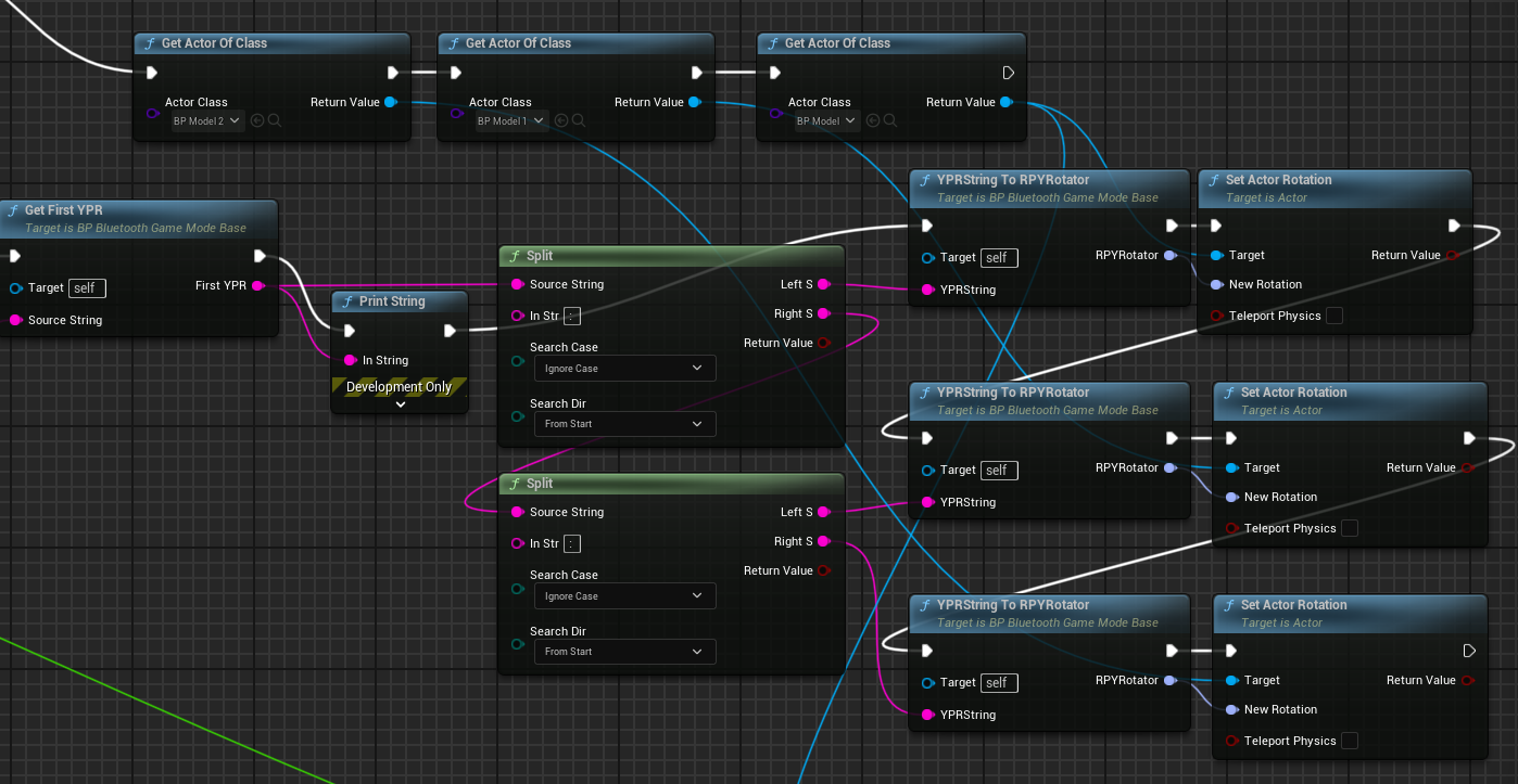
이전 코드 참고해서 만들었는데
#include"I2Cdev.h"#include"MPU6050_6Axis_MotionApps20.h"#if I2CDEV_IMPLEMENTATION == I2CDEV_ARDUINO_WIRE#include"Wire.h"#endif// class default I2C address is 0x68// specific I2C addresses may be passed as a parameter here// AD0 low = 0x68 (default for SparkFun breakout and InvenSense evaluation board)// AD0 high = 0x69
MPU6050 mpu;
//MPU6050 mpu(0x69); // <-- use for AD0 high#define OUTPUT_READABLE_YAWPITCHROLL// MPU control/status varsbool dmpReady = false; // set true if DMP init was successfuluint8_t mpuIntStatus; // holds actual interrupt status byte from MPUuint8_t devStatus; // return status after each device operation (0 = success, !0 = error)uint16_t packetSize; // expected DMP packet size (default is 42 bytes)uint16_t fifoCount; // count of all bytes currently in FIFOuint8_t fifoBuffer[64]; // FIFO storage buffer// orientation/motion vars
Quaternion q; // [w, x, y, z] quaternion container
VectorInt16 aa; // [x, y, z] accel sensor measurements
VectorInt16 aaReal; // [x, y, z] gravity-free accel sensor measurements
VectorInt16 aaWorld; // [x, y, z] world-frame accel sensor measurements
VectorFloat gravity; // [x, y, z] gravity vectorfloat euler[3]; // [psi, theta, phi] Euler angle containerfloat ypr[3]; // [yaw, pitch, roll] yaw/pitch/roll container and gravity vectorvolatilebool mpuInterrupt = false; // indicates whether MPU interrupt pin has gone highvoiddmpDataReady(){
mpuInterrupt = true;
}
#include"BluetoothSerial.h"
String device_name = "ESP32-BT-Slave";
// Check if Bluetooth is available#if !defined(CONFIG_BT_ENABLED) || !defined(CONFIG_BLUEDROID_ENABLED)#error Bluetooth is not enabled! Please run `make menuconfig` to and enable it#endif// Check Serial Port Profile#if !defined(CONFIG_BT_SPP_ENABLED)#error Serial Port Profile for Bluetooth is not available or not enabled. It is only available for the ESP32 chip.#endif
BluetoothSerial BTSerial;
int mpuPinNums[] = {36, 39, 34};
int mpuNum = sizeof(mpuPinNums) / sizeof(int);
voidInitMPU(int pinNum);
voidSendData(int pinNum);
voidsetup(){
Serial.begin(115200);
BTSerial.begin(device_name); //Bluetooth device namefor (int i = 0; i < mpuNum;i++)
pinMode(mpuPinNums[i], OUTPUT);
// join I2C bus (I2Cdev library doesn't do this automatically)#if I2CDEV_IMPLEMENTATION == I2CDEV_ARDUINO_WIRE
Wire.begin();
Wire.setClock(400000); // 400kHz I2C clock. Comment this line if having compilation difficulties#elif I2CDEV_IMPLEMENTATION == I2CDEV_BUILTIN_FASTWIRE
Fastwire::setup(400, true);
#endiffor (int i = 0; i < mpuNum;i++)
InitMPU(mpuPinNums[i]);
}
voidloop(){
for (int i = 0; i < mpuNum;i++)
SendData(mpuPinNums[i]);
Serial.println("");
}
voidInitMPU(int pinNum){
for (int i = 0; i < mpuNum; i++)
{
if (mpuPinNums[i] == pinNum)
digitalWrite(mpuPinNums[i], LOW); //set selected mpu6050 addr 0x68elsedigitalWrite(mpuPinNums[i], HIGH); //set other mpu6050 addr 0x69
}
Serial.print("start init pin ");
Serial.println(pinNum);
// initialize device
mpu.initialize();
// verify connection
Serial.println(F("Testing device connections..."));
Serial.println(mpu.testConnection() ? F("MPU6050 connection successful") : F("MPU6050 connection failed"));
// load and configure the DMP
Serial.println(F("Initializing DMP..."));
devStatus = mpu.dmpInitialize();
// supply your own gyro offsets here, scaled for min sensitivity
mpu.setXGyroOffset(220);
mpu.setYGyroOffset(76);
mpu.setZGyroOffset(-85);
mpu.setZAccelOffset(1788); // 1688 factory default for my test chip// make sure it worked (returns 0 if so)if (devStatus == 0) {
// turn on the DMP, now that it's ready
Serial.println(F("Enabling DMP..."));
mpu.setDMPEnabled(true);
// enable Arduino interrupt detection
Serial.println(F("Enabling interrupt detection (Arduino external interrupt 0)..."));
attachInterrupt(0, dmpDataReady, RISING);
//attachInterrupt(digitalPinToInterrupt(INTERRUPT_PIN), dmpDataReady, RISING);
mpuIntStatus = mpu.getIntStatus();
// set our DMP Ready flag so the main loop() function knows it's okay to use it
Serial.println(F("DMP ready! Waiting for first interrupt..."));
dmpReady = true;
// get expected DMP packet size for later comparison
packetSize = mpu.dmpGetFIFOPacketSize();
} else {
Serial.print(F("DMP Initialization failed (code "));
Serial.print(devStatus);
Serial.println(F(")"));
}
}
voidSendData(int pinNum){
for (int i = 0; i < mpuNum; i++)
{
if (mpuPinNums[i] == pinNum)
digitalWrite(mpuPinNums[i], LOW); //set selected mpu6050 addr 0x68elsedigitalWrite(mpuPinNums[i], HIGH); //set other mpu6050 addr 0x69
}
// if programming failed, don't try to do anythingif (!dmpReady) return;
mpuIntStatus = mpu.getIntStatus();
// get current FIFO count
fifoCount = mpu.getFIFOCount();
// check for overflow (this should never happen unless our code is too inefficient)if ((mpuIntStatus & 0x10) || fifoCount == 1024) {
// reset so we can continue cleanly
mpu.resetFIFO();
// otherwise, check for DMP data ready interrupt (this should happen frequently)
} elseif (mpuIntStatus & 0x02) {
// wait for correct available data length, should be a VERY short waitwhile (fifoCount < packetSize) fifoCount = mpu.getFIFOCount();
// read a packet from FIFO
mpu.getFIFOBytes(fifoBuffer, packetSize);
// track FIFO count here in case there is > 1 packet available
fifoCount -= packetSize;
#ifdef OUTPUT_READABLE_YAWPITCHROLL// display Euler angles in degrees
mpu.dmpGetQuaternion(&q, fifoBuffer);
mpu.dmpGetGravity(&gravity, &q);
mpu.dmpGetYawPitchRoll(ypr, &q, &gravity);
Serial.print(pinNum);
Serial.print(":");
Serial.print(int(ypr[0] * 180/M_PI));
Serial.print(",");
Serial.print(int(ypr[1] * 180/M_PI));
Serial.print(",");
Serial.print(int(ypr[2] * 180/M_PI));
Serial.print("/");
#endif
}
}
#include"I2Cdev.h"#include"MPU6050_6Axis_MotionApps20.h"#if I2CDEV_IMPLEMENTATION == I2CDEV_ARDUINO_WIRE#include"Wire.h"#endif// class default I2C address is 0x68// specific I2C addresses may be passed as a parameter here// AD0 low = 0x68 (default for SparkFun breakout and InvenSense evaluation board)// AD0 high = 0x69
MPU6050 mpu;
//MPU6050 mpu(0x69); // <-- use for AD0 high#define OUTPUT_READABLE_YAWPITCHROLL// MPU control/status varsbool dmpReady = false; // set true if DMP init was successfuluint8_t mpuIntStatus; // holds actual interrupt status byte from MPUuint8_t devStatus; // return status after each device operation (0 = success, !0 = error)uint16_t packetSize; // expected DMP packet size (default is 42 bytes)uint16_t fifoCount; // count of all bytes currently in FIFOuint8_t fifoBuffer[64]; // FIFO storage buffer// orientation/motion vars
Quaternion q; // [w, x, y, z] quaternion container
VectorInt16 aa; // [x, y, z] accel sensor measurements
VectorInt16 aaReal; // [x, y, z] gravity-free accel sensor measurements
VectorInt16 aaWorld; // [x, y, z] world-frame accel sensor measurements
VectorFloat gravity; // [x, y, z] gravity vectorfloat euler[3]; // [psi, theta, phi] Euler angle containerfloat ypr[3]; // [yaw, pitch, roll] yaw/pitch/roll container and gravity vectorvolatilebool mpuInterrupt = false; // indicates whether MPU interrupt pin has gone highvoiddmpDataReady(){
mpuInterrupt = true;
}
#include"BluetoothSerial.h"
String device_name = "ESP32-BT-Slave";
// Check if Bluetooth is available#if !defined(CONFIG_BT_ENABLED) || !defined(CONFIG_BLUEDROID_ENABLED)#error Bluetooth is not enabled! Please run `make menuconfig` to and enable it#endif// Check Serial Port Profile#if !defined(CONFIG_BT_SPP_ENABLED)#error Serial Port Profile for Bluetooth is not available or not enabled. It is only available for the ESP32 chip.#endif
BluetoothSerial BTSerial;
int mpuPinNums[] = {32, 33, 25};
int mpuNum = sizeof(mpuPinNums) / sizeof(int);
voidInitMPU(int pinNum);
voidSendData(int pinNum);
voidsetup(){
Serial.begin(115200);
BTSerial.begin(device_name); //Bluetooth device name
Serial.print("start init mpuNum : ");
Serial.println(mpuNum);
for (int i = 0; i < mpuNum;i++)
{
Serial.print("set pin output : ");
Serial.println(mpuPinNums[i]);
pinMode(mpuPinNums[i], OUTPUT);
}
// join I2C bus (I2Cdev library doesn't do this automatically)#if I2CDEV_IMPLEMENTATION == I2CDEV_ARDUINO_WIRE
Wire.begin();
Wire.setClock(400000); // 400kHz I2C clock. Comment this line if having compilation difficulties#elif I2CDEV_IMPLEMENTATION == I2CDEV_BUILTIN_FASTWIRE
Fastwire::setup(400, true);
#endiffor (int i = 0; i < mpuNum;i++)
InitMPU(mpuPinNums[i]);
}
voidloop(){
for (int i = 0; i < mpuNum;i++)
SendData(mpuPinNums[i]);
Serial.println("");
}
voidInitMPU(int pinNum){
for (int i = 0; i < mpuNum; i++)
{
if (mpuPinNums[i] == pinNum)
digitalWrite(mpuPinNums[i], LOW); //set selected mpu6050 addr 0x68elsedigitalWrite(mpuPinNums[i], HIGH); //set other mpu6050 addr 0x69
}
// initialize device
mpu.initialize();
// verify connection
Serial.println(F("Testing device connections..."));
Serial.println(mpu.testConnection() ? F("MPU6050 connection successful") : F("MPU6050 connection failed"));
// load and configure the DMP
Serial.println(F("Initializing DMP..."));
devStatus = mpu.dmpInitialize();
// supply your own gyro offsets here, scaled for min sensitivity
mpu.setXGyroOffset(220);
mpu.setYGyroOffset(76);
mpu.setZGyroOffset(-85);
mpu.setZAccelOffset(1788); // 1688 factory default for my test chip// make sure it worked (returns 0 if so)if (devStatus == 0) {
// turn on the DMP, now that it's ready
Serial.println(F("Enabling DMP..."));
mpu.setDMPEnabled(true);
// enable Arduino interrupt detection
Serial.println(F("Enabling interrupt detection (Arduino external interrupt 0)..."));
attachInterrupt(0, dmpDataReady, RISING);
//attachInterrupt(digitalPinToInterrupt(INTERRUPT_PIN), dmpDataReady, RISING);
mpuIntStatus = mpu.getIntStatus();
// set our DMP Ready flag so the main loop() function knows it's okay to use it
Serial.println(F("DMP ready! Waiting for first interrupt..."));
dmpReady = true;
// get expected DMP packet size for later comparison
packetSize = mpu.dmpGetFIFOPacketSize();
} else {
Serial.print(F("DMP Initialization failed (code "));
Serial.print(devStatus);
Serial.println(F(")"));
}
}
voidSendData(int pinNum){
for (int i = 0; i < mpuNum; i++)
{
if (mpuPinNums[i] == pinNum)
digitalWrite(mpuPinNums[i], LOW); //set selected mpu6050 addr 0x68elsedigitalWrite(mpuPinNums[i], HIGH); //set other mpu6050 addr 0x69
}
// if programming failed, don't try to do anythingif (!dmpReady) return;
mpuIntStatus = mpu.getIntStatus();
// get current FIFO count
fifoCount = mpu.getFIFOCount();
// check for overflow (this should never happen unless our code is too inefficient)if ((mpuIntStatus & 0x10) || fifoCount == 1024) {
// reset so we can continue cleanly
mpu.resetFIFO();
// otherwise, check for DMP data ready interrupt (this should happen frequently)
} elseif (mpuIntStatus & 0x02) {
// wait for correct available data length, should be a VERY short waitwhile (fifoCount < packetSize) fifoCount = mpu.getFIFOCount();
// read a packet from FIFO
mpu.getFIFOBytes(fifoBuffer, packetSize);
// track FIFO count here in case there is > 1 packet available
fifoCount -= packetSize;
#ifdef OUTPUT_READABLE_YAWPITCHROLL// display Euler angles in degrees
mpu.dmpGetQuaternion(&q, fifoBuffer);
mpu.dmpGetGravity(&gravity, &q);
mpu.dmpGetYawPitchRoll(ypr, &q, &gravity);
Serial.print(pinNum);
Serial.print(":");
Serial.print(int(ypr[0] * 180/M_PI));
Serial.print(",");
Serial.print(int(ypr[1] * 180/M_PI));
Serial.print(",");
Serial.print(int(ypr[2] * 180/M_PI));
Serial.print("/");
#endif
}
}
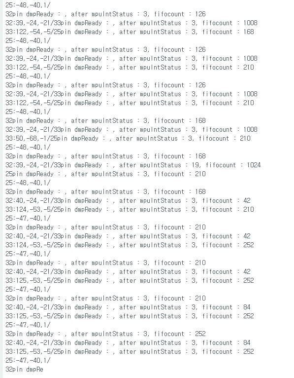
// get current FIFO count
fifoCount = mpu.getFIFOCount();
Serial.print(pinNum);
Serial.print("pin dmpReady : ");
Serial.print(", after mpuIntStatus : ");
Serial.print(mpuIntStatus);
Serial.print(", fifocount : ");
Serial.println(fifoCount);
// check for overflow (this should never happen unless our code is too inefficient)if ((mpuIntStatus & 0x10) || fifoCount == 1024) {
// reset so we can continue cleanly
mpu.resetFIFO();
#include"I2Cdev.h"#include<map>#include"MPU6050_6Axis_MotionApps20.h"#if I2CDEV_IMPLEMENTATION == I2CDEV_ARDUINO_WIRE#include"Wire.h"#endif
MPU6050 mpu;
#define OUTPUT_READABLE_YAWPITCHROLL// MPU control/status varsbool dmpReady = false; // set true if DMP init was successfuluint8_t mpuIntStatus; // holds actual interrupt status byte from MPUuint8_t devStatus; // return status after each device operation (0 = success, !0 = error)uint16_t packetSize; // expected DMP packet size (default is 42 bytes)uint16_t fifoCount; // count of all bytes currently in FIFOuint8_t fifoBuffer[64]; // FIFO storage buffer// orientation/motion vars
Quaternion q; // [w, x, y, z] quaternion container
VectorInt16 aa; // [x, y, z] accel sensor measurements
VectorInt16 aaReal; // [x, y, z] gravity-free accel sensor measurements
VectorInt16 aaWorld; // [x, y, z] world-frame accel sensor measurements
VectorFloat gravity; // [x, y, z] gravity vectorfloat euler[3]; // [psi, theta, phi] Euler angle containerfloat ypr[3]; // [yaw, pitch, roll] yaw/pitch/roll container and gravity vectorvolatilebool mpuInterrupt = false; // indicates whether MPU interrupt pin has gone highvoiddmpDataReady(){
mpuInterrupt = true;
}
#include"BluetoothSerial.h"
String device_name = "ESP32-BT-Slave";
// Check if Bluetooth is available#if !defined(CONFIG_BT_ENABLED) || !defined(CONFIG_BLUEDROID_ENABLED)#error Bluetooth is not enabled! Please run `make menuconfig` to and enable it#endif// Check Serial Port Profile#if !defined(CONFIG_BT_SPP_ENABLED)#error Serial Port Profile for Bluetooth is not available or not enabled. It is only available for the ESP32 chip.#endif
BluetoothSerial BTSerial;
int mpuPinNums[] = {32, 33, 25};
int mpuNum = sizeof(mpuPinNums) / sizeof(int);
structYPR
{int ypr[3];
};
std::map<int, YPR> yprMap;
voidInitMPU(int pinNum);
voidGetData(int pinNum);
voidSendData();
voidsetup(){
//Serial.begin(115200);
BTSerial.begin(device_name); //Bluetooth device name
YPR zeroYpr = {0, 0, 0};
for(int i = 0; i < mpuNum; i++)
yprMap.insert(std::pair<int,YPR>(mpuPinNums[i], zeroYpr));
BTSerial.print("start init mpuNum : ");
BTSerial.println(mpuNum);
for (int i = 0; i < mpuNum;i++)
{
BTSerial.print("set pin output : ");
BTSerial.println(mpuPinNums[i]);
pinMode(mpuPinNums[i], OUTPUT);
}
// join I2C bus (I2Cdev library doesn't do this automatically)#if I2CDEV_IMPLEMENTATION == I2CDEV_ARDUINO_WIRE
Wire.begin();
Wire.setClock(400000); // 400kHz I2C clock. Comment this line if having compilation difficulties#elif I2CDEV_IMPLEMENTATION == I2CDEV_BUILTIN_FASTWIRE
Fastwire::setup(400, true);
#endiffor (int i = 0; i < mpuNum;i++)
InitMPU(mpuPinNums[i]);
}
voidloop(){
for (int i = 0; i < mpuNum;i++)
GetData(mpuPinNums[i]);
SendData();
}
voidInitMPU(int pinNum){
for (int i = 0; i < mpuNum; i++)
{
if (mpuPinNums[i] == pinNum)
digitalWrite(mpuPinNums[i], LOW); //set selected mpu6050 addr 0x68elsedigitalWrite(mpuPinNums[i], HIGH); //set other mpu6050 addr 0x69
}
// initialize device
mpu.initialize();
// verify connection
BTSerial.println(F("Testing device connections..."));
BTSerial.println(mpu.testConnection() ? F("MPU6050 connection successful") : F("MPU6050 connection failed"));
// load and configure the DMP
BTSerial.println(F("Initializing DMP..."));
devStatus = mpu.dmpInitialize();
// supply your own gyro offsets here, scaled for min sensitivity
mpu.setXGyroOffset(220);
mpu.setYGyroOffset(76);
mpu.setZGyroOffset(-85);
mpu.setZAccelOffset(1788); // 1688 factory default for my test chip// make sure it worked (returns 0 if so)if (devStatus == 0) {
// turn on the DMP, now that it's ready
BTSerial.println(F("Enabling DMP..."));
mpu.setDMPEnabled(true);
// enable Arduino interrupt detection
BTSerial.println(F("Enabling interrupt detection (Arduino external interrupt 0)..."));
attachInterrupt(0, dmpDataReady, RISING);
//attachInterrupt(digitalPinToInterrupt(INTERRUPT_PIN), dmpDataReady, RISING);
mpuIntStatus = mpu.getIntStatus();
// set our DMP Ready flag so the main loop() function knows it's okay to use it
BTSerial.println(F("DMP ready! Waiting for first interrupt..."));
dmpReady = true;
// get expected DMP packet size for later comparison
packetSize = mpu.dmpGetFIFOPacketSize();
} else {
BTSerial.print(F("DMP Initialization failed (code "));
BTSerial.print(devStatus);
BTSerial.println(F(")"));
}
}
voidGetData(int pinNum){
for (int i = 0; i < mpuNum; i++)
{
if (mpuPinNums[i] == pinNum)
digitalWrite(mpuPinNums[i], LOW); //set selected mpu6050 addr 0x68elsedigitalWrite(mpuPinNums[i], HIGH); //set other mpu6050 addr 0x69
}
// if programming failed, don't try to do anythingif (!dmpReady) return;
mpuIntStatus = mpu.getIntStatus();
// get current FIFO count
fifoCount = mpu.getFIFOCount();
// check for overflow (this should never happen unless our code is too inefficient)if ((mpuIntStatus & 0x10) || fifoCount == 1024) {
// reset so we can continue cleanly
mpu.resetFIFO();
// otherwise, check for DMP data ready interrupt (this should happen frequently)
} elseif (mpuIntStatus & 0x02) {
// wait for correct available data length, should be a VERY short waitwhile (fifoCount < packetSize) fifoCount = mpu.getFIFOCount();
// read a packet from FIFO
mpu.getFIFOBytes(fifoBuffer, packetSize);
// track FIFO count here in case there is > 1 packet available
fifoCount -= packetSize;
#ifdef OUTPUT_READABLE_YAWPITCHROLL// display Euler angles in degrees
mpu.dmpGetQuaternion(&q, fifoBuffer);
mpu.dmpGetGravity(&gravity, &q);
mpu.dmpGetYawPitchRoll(ypr, &q, &gravity);
YPR tmpYpr;
tmpYpr.ypr[0] = int(ypr[0] * 180/M_PI);
tmpYpr.ypr[1] = int(ypr[1] * 180/M_PI);
tmpYpr.ypr[2] = int(ypr[2] * 180/M_PI);
yprMap[pinNum] = tmpYpr;
#endif
}
}
voidSendData(){
for (int i = 0; i < mpuNum; i++)
{
BTSerial.print(mpuPinNums[i]);
BTSerial.print(":");
BTSerial.print(yprMap[mpuPinNums[i]].ypr[0]);
BTSerial.print(",");
BTSerial.print(yprMap[mpuPinNums[i]].ypr[1]);
BTSerial.print(",");
BTSerial.print(yprMap[mpuPinNums[i]].ypr[2]);
if(i == mpuNum - 1)
BTSerial.println("");
else
BTSerial.print("/");
}
}
// join I2C bus (I2Cdev library doesn't do this automatically)#if I2CDEV_IMPLEMENTATION == I2CDEV_ARDUINO_WIRE
Wire.begin();
Wire.setClock(400000); // 400kHz I2C clock. Comment this line if having compilation difficulties#elif I2CDEV_IMPLEMENTATION == I2CDEV_BUILTIN_FASTWIRE
Fastwire::setup(400, true);
#endif
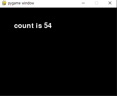
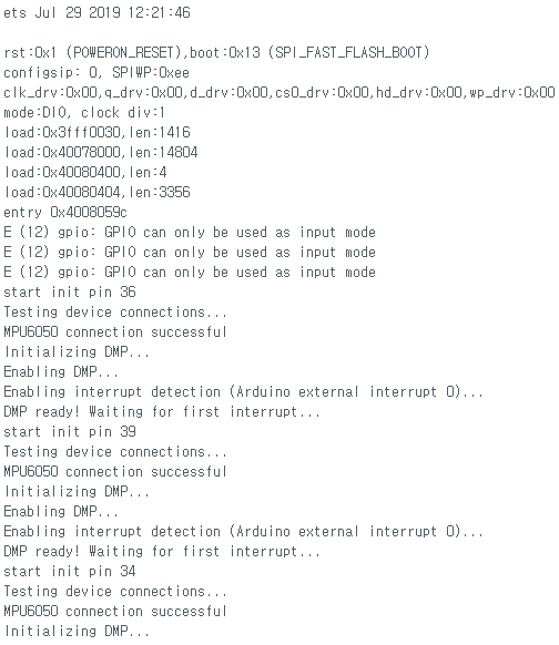
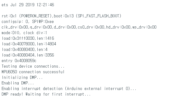
다시 업로드하고 실행시켯는데
dmp 초기화는 잘된것같지만 자세 출력이 안된다..
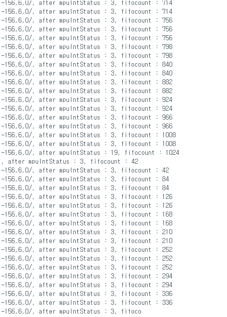
코드 중간에 mpu interrupt 기다리는 내용이 있어
여기서 막힌것으로 보인다.
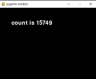
// wait for MPU interrupt or extra packet(s) availablewhile (!mpuInterrupt && fifoCount < packetSize) {
}
// reset interrupt flag and get INT_STATUS byte
mpuInterrupt = false;
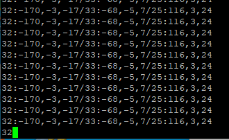
이 부분을 지우고 나면 잘 동작
어짜피 인터럽트 안써도 대충 원하는대로 동작하므로
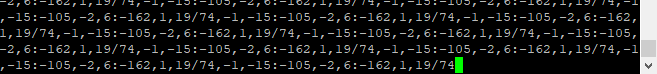
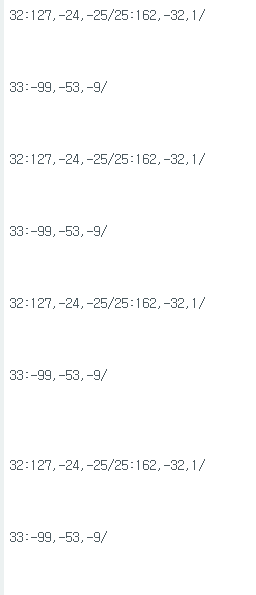
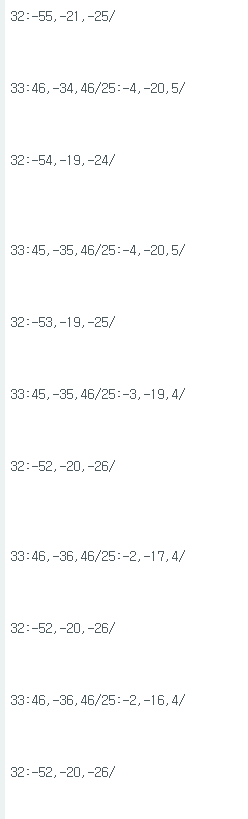
대충 FIFO가 가득차서 리프레시 할떄 뺴고는 잘나온다.
#include"I2Cdev.h"#include"MPU6050_6Axis_MotionApps20.h"#if I2CDEV_IMPLEMENTATION == I2CDEV_ARDUINO_WIRE#include"Wire.h"#endif// class default I2C address is 0x68// specific I2C addresses may be passed as a parameter here// AD0 low = 0x68 (default for SparkFun breakout and InvenSense evaluation board)// AD0 high = 0x69
MPU6050 mpu;
//MPU6050 mpu(0x69); // <-- use for AD0 high#define OUTPUT_READABLE_YAWPITCHROLL// MPU control/status varsbool dmpReady = false; // set true if DMP init was successfuluint8_t mpuIntStatus; // holds actual interrupt status byte from MPUuint8_t devStatus; // return status after each device operation (0 = success, !0 = error)uint16_t packetSize; // expected DMP packet size (default is 42 bytes)uint16_t fifoCount; // count of all bytes currently in FIFOuint8_t fifoBuffer[64]; // FIFO storage buffer// orientation/motion vars
Quaternion q; // [w, x, y, z] quaternion container
VectorInt16 aa; // [x, y, z] accel sensor measurements
VectorInt16 aaReal; // [x, y, z] gravity-free accel sensor measurements
VectorInt16 aaWorld; // [x, y, z] world-frame accel sensor measurements
VectorFloat gravity; // [x, y, z] gravity vectorfloat euler[3]; // [psi, theta, phi] Euler angle containerfloat ypr[3]; // [yaw, pitch, roll] yaw/pitch/roll container and gravity vector// packet structure for InvenSense teapot demouint8_t teapotPacket[14] = { '$', 0x02, 0,0, 0,0, 0,0, 0,0, 0x00, 0x00, '\r', '\n' };
volatilebool mpuInterrupt = false; // indicates whether MPU interrupt pin has gone highvoiddmpDataReady(){
mpuInterrupt = true;
}
#include"BluetoothSerial.h"
String device_name = "ESP32-BT-Slave";
// Check if Bluetooth is available#if !defined(CONFIG_BT_ENABLED) || !defined(CONFIG_BLUEDROID_ENABLED)#error Bluetooth is not enabled! Please run `make menuconfig` to and enable it#endif// Check Serial Port Profile#if !defined(CONFIG_BT_SPP_ENABLED)#error Serial Port Profile for Bluetooth is not available or not enabled. It is only available for the ESP32 chip.#endif
BluetoothSerial BTSerial;
voidsetup(){
// join I2C bus (I2Cdev library doesn't do this automatically)#if I2CDEV_IMPLEMENTATION == I2CDEV_ARDUINO_WIRE
Wire.begin();
Wire.setClock(400000); // 400kHz I2C clock. Comment this line if having compilation difficulties#elif I2CDEV_IMPLEMENTATION == I2CDEV_BUILTIN_FASTWIRE
Fastwire::setup(400, true);
#endif
BTSerial.begin(device_name); //Bluetooth device name
Serial.begin(115200);
// initialize device
mpu.initialize();
// verify connection
Serial.println(F("Testing device connections..."));
Serial.println(mpu.testConnection() ? F("MPU6050 connection successful") : F("MPU6050 connection failed"));
// load and configure the DMP
Serial.println(F("Initializing DMP..."));
devStatus = mpu.dmpInitialize();
// supply your own gyro offsets here, scaled for min sensitivity
mpu.setXGyroOffset(220);
mpu.setYGyroOffset(76);
mpu.setZGyroOffset(-85);
mpu.setZAccelOffset(1788); // 1688 factory default for my test chip// make sure it worked (returns 0 if so)if (devStatus == 0) {
// turn on the DMP, now that it's ready
Serial.println(F("Enabling DMP..."));
mpu.setDMPEnabled(true);
// enable Arduino interrupt detection
Serial.println(F("Enabling interrupt detection (Arduino external interrupt 0)..."));
attachInterrupt(0, dmpDataReady, RISING);
//attachInterrupt(digitalPinToInterrupt(INTERRUPT_PIN), dmpDataReady, RISING);
mpuIntStatus = mpu.getIntStatus();
// set our DMP Ready flag so the main loop() function knows it's okay to use it
Serial.println(F("DMP ready! Waiting for first interrupt..."));
dmpReady = true;
// get expected DMP packet size for later comparison
packetSize = mpu.dmpGetFIFOPacketSize();
} else {
Serial.print(F("DMP Initialization failed (code "));
Serial.print(devStatus);
Serial.println(F(")"));
}
}
voidloop(){
// if programming failed, don't try to do anythingif (!dmpReady) return;
mpuIntStatus = mpu.getIntStatus();
// get current FIFO count
fifoCount = mpu.getFIFOCount();
/*
Serial.print(", after mpuIntStatus : ");
Serial.print(mpuIntStatus);
Serial.print(", fifocount : ");
Serial.println(fifoCount);
*/// check for overflow (this should never happen unless our code is too inefficient)if ((mpuIntStatus & 0x10) || fifoCount == 1024) {
// reset so we can continue cleanly
mpu.resetFIFO();
// otherwise, check for DMP data ready interrupt (this should happen frequently)
} elseif (mpuIntStatus & 0x02) {
// wait for correct available data length, should be a VERY short waitwhile (fifoCount < packetSize) fifoCount = mpu.getFIFOCount();
// read a packet from FIFO
mpu.getFIFOBytes(fifoBuffer, packetSize);
// track FIFO count here in case there is > 1 packet available// (this lets us immediately read more without waiting for an interrupt)
fifoCount -= packetSize;
#ifdef OUTPUT_READABLE_YAWPITCHROLL// display Euler angles in degrees
mpu.dmpGetQuaternion(&q, fifoBuffer);
mpu.dmpGetGravity(&gravity, &q);
mpu.dmpGetYawPitchRoll(ypr, &q, &gravity);
//Serial.print(pinNum);//Serial.print(":");
Serial.print(int(ypr[0] * 180/M_PI));
Serial.print(",");
Serial.print(int(ypr[1] * 180/M_PI));
Serial.print(",");
Serial.print(int(ypr[2] * 180/M_PI));
Serial.print("/");
#endif
}
delay(20);
}
// This example code is in the Public Domain (or CC0 licensed, at your option.)// By Evandro Copercini - 2018//// This example creates a bridge between Serial and Classical Bluetooth (SPP)// and also demonstrate that SerialBT have the same functionalities of a normal Serial// Note: Pairing is authenticated automatically by this device#include"BluetoothSerial.h"
String device_name = "ESP32-BT-Slave";
// Check if Bluetooth is available#if !defined(CONFIG_BT_ENABLED) || !defined(CONFIG_BLUEDROID_ENABLED)#error Bluetooth is not enabled! Please run `make menuconfig` to and enable it#endif// Check Serial Port Profile#if !defined(CONFIG_BT_SPP_ENABLED)#error Serial Port Profile for Bluetooth is not available or not enabled. It is only available for the ESP32 chip.#endif
BluetoothSerial SerialBT;
voidsetup(){
Serial.begin(115200);
SerialBT.begin(device_name); //Bluetooth device name//SerialBT.deleteAllBondedDevices(); // Uncomment this to delete paired devices; Must be called after begin
Serial.printf("The device with name \"%s\" is started.\nNow you can pair it with Bluetooth!\n", device_name.c_str());
}
voidloop(){
if (Serial.available()) {
SerialBT.write(Serial.read());
}
if (SerialBT.available()) {
Serial.write(SerialBT.read());
}
delay(20);
}