void SendData(int pinNum)
{
for (int i = 0; i < 2; i++)
{
if (mpuPinNums[i] == pinNum)
digitalWrite(mpuPinNums[i], LOW); //set selected mpu6050 addr 0x68
else
digitalWrite(mpuPinNums[i], HIGH); //set other mpu6050 addr 0x69
}
// if programming failed, don't try to do anything
if (!dmpReady) return;
// wait for MPU interrupt or extra packet(s) available
while (!mpuInterrupt && fifoCount < packetSize) {
}
// reset interrupt flag and get INT_STATUS byte
mpuInterrupt = false;
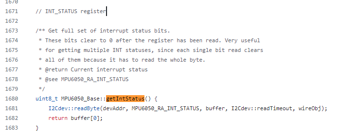
mpuIntStatus = mpu.getIntStatus();
// get current FIFO count
fifoCount = mpu.getFIFOCount();
// check for overflow (this should never happen unless our code is too inefficient)
if ((mpuIntStatus & 0x10) || fifoCount == 1024) {
// reset so we can continue cleanly
mpu.resetFIFO();
// otherwise, check for DMP data ready interrupt (this should happen frequently)
} else if (mpuIntStatus & 0x02) {
// wait for correct available data length, should be a VERY short wait
while (fifoCount < packetSize) fifoCount = mpu.getFIFOCount();
// read a packet from FIFO
mpu.getFIFOBytes(fifoBuffer, packetSize);
// track FIFO count here in case there is > 1 packet available
// (this lets us immediately read more without waiting for an interrupt)
fifoCount -= packetSize;
#ifdef OUTPUT_READABLE_YAWPITCHROLL
// display Euler angles in degrees
mpu.dmpGetQuaternion(&q, fifoBuffer);
mpu.dmpGetGravity(&gravity, &q);
mpu.dmpGetYawPitchRoll(ypr, &q, &gravity);
BTSerial.print(pinNum);
BTSerial.print(":");
BTSerial.print(int(ypr[0] * 180/M_PI));
BTSerial.print(",");
BTSerial.print(int(ypr[1] * 180/M_PI));
BTSerial.print(",");
BTSerial.print(int(ypr[2] * 180/M_PI));
BTSerial.print("/");
#endif
}
}
mpu 상태가져오기전에 사용되는 값들 출력시켜봣는데
    Serial.println("");
    Serial.print(pinNum);
    Serial.print("pin dmpReady : ");
    Serial.print(dmpReady);
    Serial.print(", before mpuInterrupt : ");
    Serial.print(mpuInterrupt);
    Serial.print(", fifocount : ");
    Serial.println(fifoCount);

    // if programming failed, don't try to do anything
    if (!dmpReady) return;

    // wait for MPU interrupt or extra packet(s) available
    while (!mpuInterrupt && fifoCount < packetSize) {
    }
이것만으로 어쩔때 나오고 어쩔때 안나오는지 판단할수가 없엇음.
이번에는
상태랑 피포카운트 출력하도록 수정
    // reset interrupt flag and get INT_STATUS byte
    mpuInterrupt = false;
    mpuIntStatus = mpu.getIntStatus();

    // get current FIFO count
    fifoCount = mpu.getFIFOCount();
    Serial.print(", after mpuIntStatus : ");
    Serial.print(mpuIntStatus);
    Serial.print(", fifocount : ");
    Serial.println(fifoCount);

    // check for overflow (this should never happen unless our code is too inefficient)
    if ((mpuIntStatus & 0x10) || fifoCount == 1024) {
        // reset so we can continue cleanly
        mpu.resetFIFO();

    // otherwise, check for DMP data ready interrupt (this should happen frequently)
    } else if (mpuIntStatus & 0x02) {
        // wait for correct available data length, should be a VERY short wait
        while (fifoCount < packetSize) fifoCount = mpu.getFIFOCount();

        // read a packet from FIFO
        mpu.getFIFOBytes(fifoBuffer, packetSize);

        // track FIFO count here in case there is > 1 packet available
        // (this lets us immediately read more without waiting for an interrupt)
        fifoCount -= packetSize;

        #ifdef OUTPUT_READABLE_YAWPITCHROLL
            // display Euler angles in degrees
            mpu.dmpGetQuaternion(&q, fifoBuffer);
            mpu.dmpGetGravity(&gravity, &q);
            mpu.dmpGetYawPitchRoll(ypr, &q, &gravity);
            Serial.print(pinNum);
            Serial.print(":");
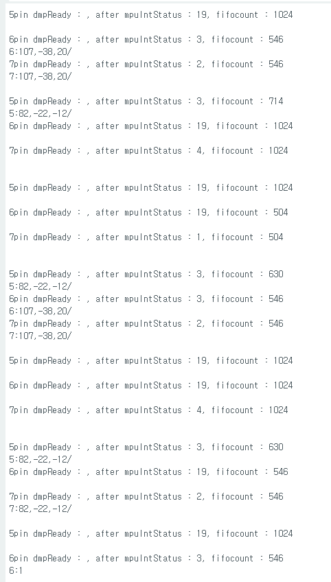
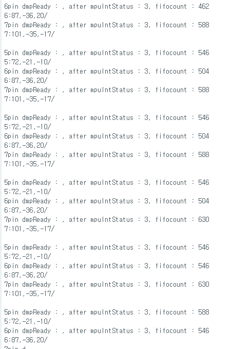
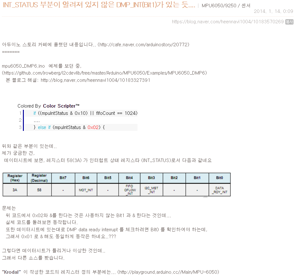
위 코드 대로 mpuIntStatus 가 2일때만 진입해서 출력하는걸 확인
2 외에
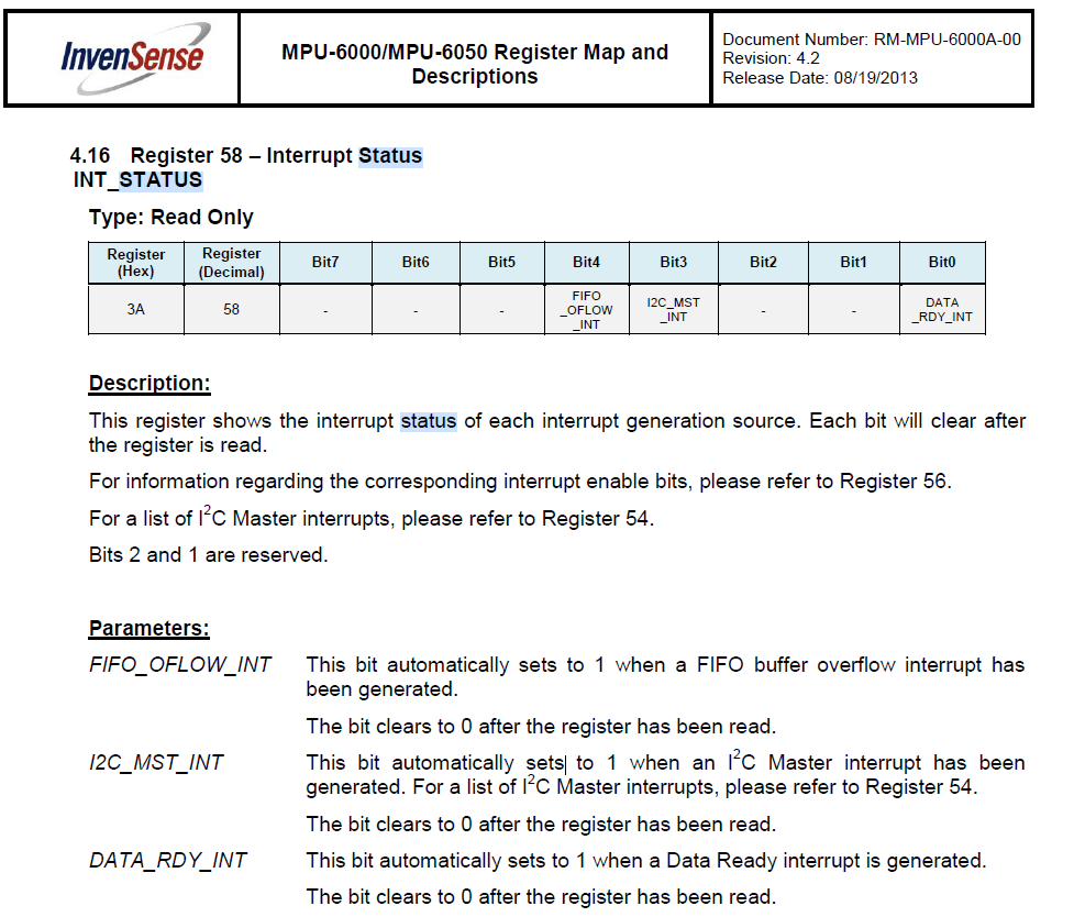
1, 3, 4, 19가 자주 발생한다.
잠깐 지금 보니 6, 7때 같은값을 가져오고있었네
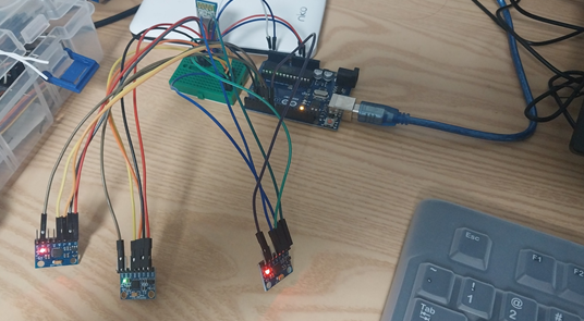
mpu3개 연결했는데
루프문을 몇군대 잘못하기도하고
세번째 mpu를 반대로 놓거나
핀아웃을 안해놔서 안떳다.
거기다가 블루투스때문에 보드레이트를 9600 해놨었는데
115200으로 했을때 더 잘나온다.
//RXD3, TXD4
SoftwareSerial BTSerial(4, 3);
int mpuPinNums[] = {5, 6, 7};
int mpuNum = sizeof(mpuPinNums) / sizeof(int);


void InitMPU(int pinNum);
void SendData(int pinNum);

void setup() {
  for (int i = 0; i < mpuNum;i++)
    pinMode(mpuPinNums[i], OUTPUT);

  Serial.begin(115200);

  #if I2CDEV_IMPLEMENTATION == I2CDEV_ARDUINO_WIRE
      Wire.begin();
      TWBR = 24; // 400kHz I2C clock (200kHz if CPU is 8MHz)
  #elif I2CDEV_IMPLEMENTATION == I2CDEV_BUILTIN_FASTWIRE
      Fastwire::setup(400, true);
  #endif

  while (!Serial); // wait for Leonardo enumeration, others continue immediately

  for (int i = 0; i < mpuNum;i++)
    InitMPU(mpuPinNums[i]);
}


void loop() {

  for (int i = 0; i < mpuNum;i++)
    SendData(mpuPinNums[i]);

  Serial.println("");
}


void InitMPU(int pinNum)
{
  for (int i = 0; i < mpuNum; i++)
  {
    if (mpuPinNums[i] == pinNum)
      digitalWrite(pinNum, LOW);  //set selected mpu6050 addr 0x68
    else
      digitalWrite(mpuPinNums[i], HIGH);  //set other mpu6050 addr 0x69
  }
  Serial.print("start init pin ");
  Serial.println(pinNum);


  // initialize device
  mpu.initialize();

  // verify connection
  Serial.println(F("Testing device connections..."));
  Serial.println(mpu.testConnection() ? F("MPU6050 connection successful") : F("MPU6050 connection failed"));

  // load and configure the DMP
  Serial.println(F("Initializing DMP..."));
  devStatus = mpu.dmpInitialize();

  // supply your own gyro offsets here, scaled for min sensitivity
  mpu.setXGyroOffset(220);
  mpu.setYGyroOffset(76);
  mpu.setZGyroOffset(-85);
  mpu.setZAccelOffset(1788); // 1688 factory default for my test chip

  // make sure it worked (returns 0 if so)
  if (devStatus == 0) {
      // turn on the DMP, now that it's ready
      Serial.println(F("Enabling DMP..."));
      mpu.setDMPEnabled(true);

      // enable Arduino interrupt detection
      Serial.println(F("Enabling interrupt detection (Arduino external interrupt 0)..."));
      attachInterrupt(0, dmpDataReady, RISING);
      //attachInterrupt(digitalPinToInterrupt(INTERRUPT_PIN), dmpDataReady, RISING);

      mpuIntStatus = mpu.getIntStatus();

      // set our DMP Ready flag so the main loop() function knows it's okay to use it
      Serial.println(F("DMP ready! Waiting for first interrupt..."));
      dmpReady = true;

      // get expected DMP packet size for later comparison
      packetSize = mpu.dmpGetFIFOPacketSize();
  } else {
      Serial.print(F("DMP Initialization failed (code "));
      Serial.print(devStatus);
      Serial.println(F(")"));
  }
}

void SendData(int pinNum)
{
  for (int i = 0; i < mpuNum; i++)
  {
    if (mpuPinNums[i] == pinNum)
      digitalWrite(mpuPinNums[i], LOW);  //set selected mpu6050 addr 0x68
    else
      digitalWrite(mpuPinNums[i], HIGH);  //set other mpu6050 addr 0x69
  }


  Serial.println("");

  Serial.print(pinNum);
  Serial.print("pin dmpReady : ");

  // if programming failed, don't try to do anything
  if (!dmpReady) return;

  // wait for MPU interrupt or extra packet(s) available
  while (!mpuInterrupt && fifoCount < packetSize) {
  }

  // reset interrupt flag and get INT_STATUS byte
  mpuInterrupt = false;
  mpuIntStatus = mpu.getIntStatus();

  // get current FIFO count
  fifoCount = mpu.getFIFOCount();
  Serial.print(", after mpuIntStatus : ");
  Serial.print(mpuIntStatus);
  Serial.print(", fifocount : ");
  Serial.println(fifoCount);

  // check for overflow (this should never happen unless our code is too inefficient)
  if ((mpuIntStatus & 0x10) || fifoCount == 1024) {
      // reset so we can continue cleanly
      mpu.resetFIFO();

  // otherwise, check for DMP data ready interrupt (this should happen frequently)
  } else if (mpuIntStatus & 0x02) {
      // wait for correct available data length, should be a VERY short wait
      while (fifoCount < packetSize) fifoCount = mpu.getFIFOCount();

      // read a packet from FIFO
      mpu.getFIFOBytes(fifoBuffer, packetSize);

      // track FIFO count here in case there is > 1 packet available
      // (this lets us immediately read more without waiting for an interrupt)
      fifoCount -= packetSize;

      #ifdef OUTPUT_READABLE_YAWPITCHROLL
          // display Euler angles in degrees
          mpu.dmpGetQuaternion(&q, fifoBuffer);
          mpu.dmpGetGravity(&gravity, &q);
          mpu.dmpGetYawPitchRoll(ypr, &q, &gravity);
          Serial.print(pinNum);
          Serial.print(":");
          Serial.print(int(ypr[0] * 180/M_PI));
          Serial.print(",");
          Serial.print(int(ypr[1] * 180/M_PI));
          Serial.print(",");
          Serial.print(int(ypr[2] * 180/M_PI));
          Serial.print("/");
      #endif
  }
}
#include "I2Cdev.h"
#include <SoftwareSerial.h>
#include "MPU6050_6Axis_MotionApps20.h"
#if I2CDEV_IMPLEMENTATION == I2CDEV_ARDUINO_WIRE
#include "Wire.h"
#endif
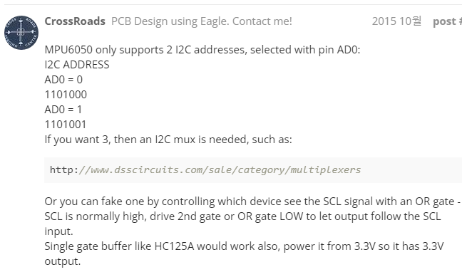
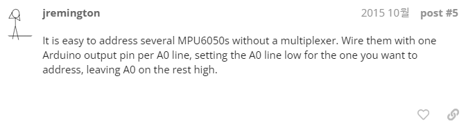
// class default I2C address is 0x68
// specific I2C addresses may be passed as a parameter here
// AD0 low = 0x68 (default for SparkFun breakout and InvenSense evaluation board)
// AD0 high = 0x69
MPU6050 mpu;
//MPU6050 mpu(0x69); // <-- use for AD0 high
#define OUTPUT_READABLE_YAWPITCHROLL
#define LED_PIN 13 // (Arduino is 13, Teensy is 11, Teensy++ is 6)
bool blinkState = false;
// MPU control/status vars
bool dmpReady = false; // set true if DMP init was successful
uint8_t mpuIntStatus; // holds actual interrupt status byte from MPU
uint8_t devStatus; // return status after each device operation (0 = success, !0 = error)
uint16_t packetSize; // expected DMP packet size (default is 42 bytes)
uint16_t fifoCount; // count of all bytes currently in FIFO
uint8_t fifoBuffer[64]; // FIFO storage buffer
// orientation/motion vars
Quaternion q; // [w, x, y, z] quaternion container
VectorInt16 aa; // [x, y, z] accel sensor measurements
VectorInt16 aaReal; // [x, y, z] gravity-free accel sensor measurements
VectorInt16 aaWorld; // [x, y, z] world-frame accel sensor measurements
VectorFloat gravity; // [x, y, z] gravity vector
float euler[3]; // [psi, theta, phi] Euler angle container
float ypr[3]; // [yaw, pitch, roll] yaw/pitch/roll container and gravity vector
// packet structure for InvenSense teapot demo
uint8_t teapotPacket[14] = { '$', 0x02, 0,0, 0,0, 0,0, 0,0, 0x00, 0x00, '\r', '\n' };
volatile bool mpuInterrupt = false; // indicates whether MPU interrupt pin has gone high
void dmpDataReady() {
mpuInterrupt = true;
}
//RXD3, TXD4
SoftwareSerial BTSerial(4, 3);
int mpuPinNums[] = {5, 6};
void InitMPU(int pinNum);
void SendData(int pinNum);
void setup() {
pinMode(5, OUTPUT);//MPU #1
pinMode(6, OUTPUT);//MPU #2
Serial.begin(115200);
#if I2CDEV_IMPLEMENTATION == I2CDEV_ARDUINO_WIRE
Wire.begin();
TWBR = 24; // 400kHz I2C clock (200kHz if CPU is 8MHz)
#elif I2CDEV_IMPLEMENTATION == I2CDEV_BUILTIN_FASTWIRE
Fastwire::setup(400, true);
#endif
while (!Serial); // wait for Leonardo enumeration, others continue immediately
for (int i = 0; i<2; i++)
InitMPU(mpuPinNums[i]);
}
void loop() {
for (int i = 0; i<2; i++)
SendData(mpuPinNums[i]);
Serial.println("");
delay(100);
}
void InitMPU(int pinNum)
{
for (int i = 0; i < 2; i++)
{
if (mpuPinNums[i] == pinNum)
digitalWrite(pinNum, LOW); //set selected mpu6050 addr 0x68
else
digitalWrite(mpuPinNums[i], HIGH); //set other mpu6050 addr 0x69
}
Serial.print("start init pin ");
Serial.println(pinNum);
// initialize device
mpu.initialize();
// verify connection
Serial.println(F("Testing device connections..."));
Serial.println(mpu.testConnection() ? F("MPU6050 connection successful") : F("MPU6050 connection failed"));
// load and configure the DMP
Serial.println(F("Initializing DMP..."));
devStatus = mpu.dmpInitialize();
// supply your own gyro offsets here, scaled for min sensitivity
mpu.setXGyroOffset(220);
mpu.setYGyroOffset(76);
mpu.setZGyroOffset(-85);
mpu.setZAccelOffset(1788); // 1688 factory default for my test chip
// make sure it worked (returns 0 if so)
if (devStatus == 0) {
// turn on the DMP, now that it's ready
Serial.println(F("Enabling DMP..."));
mpu.setDMPEnabled(true);
// enable Arduino interrupt detection
Serial.println(F("Enabling interrupt detection (Arduino external interrupt 0)..."));
attachInterrupt(0, dmpDataReady, RISING);
//attachInterrupt(digitalPinToInterrupt(INTERRUPT_PIN), dmpDataReady, RISING);
mpuIntStatus = mpu.getIntStatus();
// set our DMP Ready flag so the main loop() function knows it's okay to use it
Serial.println(F("DMP ready! Waiting for first interrupt..."));
dmpReady = true;
// get expected DMP packet size for later comparison
packetSize = mpu.dmpGetFIFOPacketSize();
} else {
Serial.print(F("DMP Initialization failed (code "));
Serial.print(devStatus);
Serial.println(F(")"));
}
}
void SendData(int pinNum)
{
for (int i = 0; i < 2; i++)
{
if (mpuPinNums[i] == pinNum)
digitalWrite(mpuPinNums[i], LOW); //set selected mpu6050 addr 0x68
else
digitalWrite(mpuPinNums[i], HIGH); //set other mpu6050 addr 0x69
}
// if programming failed, don't try to do anything
if (!dmpReady) return;
// wait for MPU interrupt or extra packet(s) available
while (!mpuInterrupt && fifoCount < packetSize) {
}
// reset interrupt flag and get INT_STATUS byte
mpuInterrupt = false;
mpuIntStatus = mpu.getIntStatus();
// get current FIFO count
fifoCount = mpu.getFIFOCount();
// check for overflow (this should never happen unless our code is too inefficient)
if ((mpuIntStatus & 0x10) || fifoCount == 1024) {
// reset so we can continue cleanly
mpu.resetFIFO();
// otherwise, check for DMP data ready interrupt (this should happen frequently)
} else if (mpuIntStatus & 0x02) {
// wait for correct available data length, should be a VERY short wait
while (fifoCount < packetSize) fifoCount = mpu.getFIFOCount();
// read a packet from FIFO
mpu.getFIFOBytes(fifoBuffer, packetSize);
// track FIFO count here in case there is > 1 packet available
// (this lets us immediately read more without waiting for an interrupt)
fifoCount -= packetSize;
#ifdef OUTPUT_READABLE_YAWPITCHROLL
// display Euler angles in degrees
mpu.dmpGetQuaternion(&q, fifoBuffer);
mpu.dmpGetGravity(&gravity, &q);
mpu.dmpGetYawPitchRoll(ypr, &q, &gravity);
Serial.print(pinNum);
Serial.print(":");
Serial.print(int(ypr[0] * 180/M_PI));
Serial.print(",");
Serial.print(int(ypr[1] * 180/M_PI));
Serial.print(",");
Serial.print(int(ypr[2] * 180/M_PI));
Serial.print("/");
#endif
}
}
기존의 초기화, 각 가져오는 코드는 따로빼고
AD0 핀들 output 설정
int mpuPinNums[] = {5, 6};

void InitMPU(int pinNum);
void SendData(int pinNum);

void setup() {
  pinMode(5, OUTPUT);//MPU #1
  pinMode(6, OUTPUT);//MPU #2

  Serial.begin(115200);

  #if I2CDEV_IMPLEMENTATION == I2CDEV_ARDUINO_WIRE
      Wire.begin();
      TWBR = 24; // 400kHz I2C clock (200kHz if CPU is 8MHz)
  #elif I2CDEV_IMPLEMENTATION == I2CDEV_BUILTIN_FASTWIRE
      Fastwire::setup(400, true);
  #endif

  while (!Serial); // wait for Leonardo enumeration, others continue immediately

  for (int i = 0; i<2; i++)
    InitMPU(mpuPinNums[i]);
}
초기화 코드에서는
모든 mpu를 돌아가면서 초기화하는데
선택된 mpu만 주소를 0x68로 설정하고 수행
나머지는 초기화전 0x69로 설정
void InitMPU(int pinNum)
{
  for (int i = 0; i < 2; i++)
  {
    if (mpuPinNums[i] == pinNum)
      digitalWrite(pinNum, LOW);  //set selected mpu6050 addr 0x68
    else
      digitalWrite(mpuPinNums[i], HIGH);  //set other mpu6050 addr 0x69
  }
  Serial.print("start init pin ");
  Serial.println(pinNum);


  // initialize device
  mpu.initialize();

  // verify connection
  Serial.println(F("Testing device connections..."));
  Serial.println(mpu.testConnection() ? F("MPU6050 connection successful") : F("MPU6050 connection failed"));

  // load and configure the DMP
  Serial.println(F("Initializing DMP..."));
  devStatus = mpu.dmpInitialize();

  // supply your own gyro offsets here, scaled for min sensitivity
  mpu.setXGyroOffset(220);
  mpu.setYGyroOffset(76);
  mpu.setZGyroOffset(-85);
  mpu.setZAccelOffset(1788); // 1688 factory default for my test chip

  // make sure it worked (returns 0 if so)
  if (devStatus == 0) {
      // turn on the DMP, now that it's ready
      Serial.println(F("Enabling DMP..."));
      mpu.setDMPEnabled(true);

      // enable Arduino interrupt detection
      Serial.println(F("Enabling interrupt detection (Arduino external interrupt 0)..."));
      attachInterrupt(0, dmpDataReady, RISING);
      //attachInterrupt(digitalPinToInterrupt(INTERRUPT_PIN), dmpDataReady, RISING);

      mpuIntStatus = mpu.getIntStatus();

      // set our DMP Ready flag so the main loop() function knows it's okay to use it
      Serial.println(F("DMP ready! Waiting for first interrupt..."));
      dmpReady = true;

      // get expected DMP packet size for later comparison
      packetSize = mpu.dmpGetFIFOPacketSize();
  } else {
      Serial.print(F("DMP Initialization failed (code "));
      Serial.print(devStatus);
      Serial.println(F(")"));
  }
}
루프의 경우 각 mpu 돌아가면서 각 출력하고 딜레이 주는식으로 정리
void loop() {
  for (int i = 0; i<2; i++)
    SendData(mpuPinNums[i]);

  Serial.println("");
  delay(50);
}
senddata의 경우
초기화때와 마찬가지로 선택된 mpu만 가져오도록 설정
void SendData(int pinNum)
{
    for (int i = 0; i < 2; i++)
    {
      if (mpuPinNums[i] == pinNum)
        digitalWrite(mpuPinNums[i], LOW);  //set selected mpu6050 addr 0x68
      else
        digitalWrite(mpuPinNums[i], HIGH);  //set other mpu6050 addr 0x69
    }

    // if programming failed, don't try to do anything
    if (!dmpReady) return;

    // wait for MPU interrupt or extra packet(s) available
    while (!mpuInterrupt && fifoCount < packetSize) {
    }

    // reset interrupt flag and get INT_STATUS byte
    mpuInterrupt = false;
    mpuIntStatus = mpu.getIntStatus();

    // get current FIFO count
    fifoCount = mpu.getFIFOCount();

    // check for overflow (this should never happen unless our code is too inefficient)
    if ((mpuIntStatus & 0x10) || fifoCount == 1024) {
        // reset so we can continue cleanly
        mpu.resetFIFO();

    // otherwise, check for DMP data ready interrupt (this should happen frequently)
    } else if (mpuIntStatus & 0x02) {
        // wait for correct available data length, should be a VERY short wait
        while (fifoCount < packetSize) fifoCount = mpu.getFIFOCount();

        // read a packet from FIFO
        mpu.getFIFOBytes(fifoBuffer, packetSize);

        // track FIFO count here in case there is > 1 packet available
        // (this lets us immediately read more without waiting for an interrupt)
        fifoCount -= packetSize;

        #ifdef OUTPUT_READABLE_YAWPITCHROLL
            // display Euler angles in degrees
            mpu.dmpGetQuaternion(&q, fifoBuffer);
            mpu.dmpGetGravity(&gravity, &q);
            mpu.dmpGetYawPitchRoll(ypr, &q, &gravity);
            Serial.print(pinNum);
            Serial.print(":");
            Serial.print(int(ypr[0] * 180/M_PI));
            Serial.print(",");
            Serial.print(int(ypr[1] * 180/M_PI));
            Serial.print(",");
            Serial.print(int(ypr[2] * 180/M_PI));
            Serial.print("/");
        #endif
    }
}
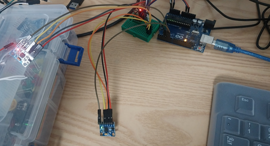
이 코드는 배터리가 아닌 PC전원으로 쓰면서
115200 시리얼 통신으로 가져와 쓰드록 정리
#include "I2Cdev.h"
#include <SoftwareSerial.h>

#include "MPU6050_6Axis_MotionApps20.h"
#if I2CDEV_IMPLEMENTATION == I2CDEV_ARDUINO_WIRE
    #include "Wire.h"
#endif

// class default I2C address is 0x68
// specific I2C addresses may be passed as a parameter here
// AD0 low = 0x68 (default for SparkFun breakout and InvenSense evaluation board)
// AD0 high = 0x69
MPU6050 mpu;
//MPU6050 mpu(0x69); // <-- use for AD0 high

#define OUTPUT_READABLE_YAWPITCHROLL


#define LED_PIN 13 // (Arduino is 13, Teensy is 11, Teensy++ is 6)
bool blinkState = false;

// MPU control/status vars
bool dmpReady = false;  // set true if DMP init was successful
uint8_t mpuIntStatus;   // holds actual interrupt status byte from MPU
uint8_t devStatus;      // return status after each device operation (0 = success, !0 = error)
uint16_t packetSize;    // expected DMP packet size (default is 42 bytes)
uint16_t fifoCount;     // count of all bytes currently in FIFO
uint8_t fifoBuffer[64]; // FIFO storage buffer

// orientation/motion vars
Quaternion q;           // [w, x, y, z]         quaternion container
VectorInt16 aa;         // [x, y, z]            accel sensor measurements
VectorInt16 aaReal;     // [x, y, z]            gravity-free accel sensor measurements
VectorInt16 aaWorld;    // [x, y, z]            world-frame accel sensor measurements
VectorFloat gravity;    // [x, y, z]            gravity vector
float euler[3];         // [psi, theta, phi]    Euler angle container
float ypr[3];           // [yaw, pitch, roll]   yaw/pitch/roll container and gravity vector

// packet structure for InvenSense teapot demo
uint8_t teapotPacket[14] = { '$', 0x02, 0,0, 0,0, 0,0, 0,0, 0x00, 0x00, '\r', '\n' };


volatile bool mpuInterrupt = false;     // indicates whether MPU interrupt pin has gone high
void dmpDataReady() {
    mpuInterrupt = true;
}


//RXD3, TXD4
SoftwareSerial BTSerial(4, 3);
int mpuPinNums[] = {5, 6};

void InitMPU(int pinNum);
void SendData(int pinNum);

void setup() {
  pinMode(5, OUTPUT);//MPU #1
  pinMode(6, OUTPUT);//MPU #2

  Serial.begin(115200);

  #if I2CDEV_IMPLEMENTATION == I2CDEV_ARDUINO_WIRE
      Wire.begin();
      TWBR = 24; // 400kHz I2C clock (200kHz if CPU is 8MHz)
  #elif I2CDEV_IMPLEMENTATION == I2CDEV_BUILTIN_FASTWIRE
      Fastwire::setup(400, true);
  #endif

  while (!Serial); // wait for Leonardo enumeration, others continue immediately

  for (int i = 0; i<2; i++)
    InitMPU(mpuPinNums[i]);
}


void loop() {
  for (int i = 0; i<2; i++)
    SendData(mpuPinNums[i]);

  Serial.println("");
  delay(50);
}


void InitMPU(int pinNum)
{
  for (int i = 0; i < 2; i++)
  {
    if (mpuPinNums[i] == pinNum)
      digitalWrite(pinNum, LOW);  //set selected mpu6050 addr 0x68
    else
      digitalWrite(mpuPinNums[i], HIGH);  //set other mpu6050 addr 0x69
  }
  Serial.print("start init pin ");
  Serial.println(pinNum);


  // initialize device
  mpu.initialize();

  // verify connection
  Serial.println(F("Testing device connections..."));
  Serial.println(mpu.testConnection() ? F("MPU6050 connection successful") : F("MPU6050 connection failed"));

  // load and configure the DMP
  Serial.println(F("Initializing DMP..."));
  devStatus = mpu.dmpInitialize();

  // supply your own gyro offsets here, scaled for min sensitivity
  mpu.setXGyroOffset(220);
  mpu.setYGyroOffset(76);
  mpu.setZGyroOffset(-85);
  mpu.setZAccelOffset(1788); // 1688 factory default for my test chip

  // make sure it worked (returns 0 if so)
  if (devStatus == 0) {
      // turn on the DMP, now that it's ready
      Serial.println(F("Enabling DMP..."));
      mpu.setDMPEnabled(true);

      // enable Arduino interrupt detection
      Serial.println(F("Enabling interrupt detection (Arduino external interrupt 0)..."));
      attachInterrupt(0, dmpDataReady, RISING);
      //attachInterrupt(digitalPinToInterrupt(INTERRUPT_PIN), dmpDataReady, RISING);

      mpuIntStatus = mpu.getIntStatus();

      // set our DMP Ready flag so the main loop() function knows it's okay to use it
      Serial.println(F("DMP ready! Waiting for first interrupt..."));
      dmpReady = true;

      // get expected DMP packet size for later comparison
      packetSize = mpu.dmpGetFIFOPacketSize();
  } else {
      Serial.print(F("DMP Initialization failed (code "));
      Serial.print(devStatus);
      Serial.println(F(")"));
  }
}

void SendData(int pinNum)
{
    for (int i = 0; i < 2; i++)
    {
      if (mpuPinNums[i] == pinNum)
        digitalWrite(mpuPinNums[i], LOW);  //set selected mpu6050 addr 0x68
      else
        digitalWrite(mpuPinNums[i], HIGH);  //set other mpu6050 addr 0x69
    }

    // if programming failed, don't try to do anything
    if (!dmpReady) return;

    // wait for MPU interrupt or extra packet(s) available
    while (!mpuInterrupt && fifoCount < packetSize) {
    }

    // reset interrupt flag and get INT_STATUS byte
    mpuInterrupt = false;
    mpuIntStatus = mpu.getIntStatus();

    // get current FIFO count
    fifoCount = mpu.getFIFOCount();

    // check for overflow (this should never happen unless our code is too inefficient)
    if ((mpuIntStatus & 0x10) || fifoCount == 1024) {
        // reset so we can continue cleanly
        mpu.resetFIFO();

    // otherwise, check for DMP data ready interrupt (this should happen frequently)
    } else if (mpuIntStatus & 0x02) {
        // wait for correct available data length, should be a VERY short wait
        while (fifoCount < packetSize) fifoCount = mpu.getFIFOCount();

        // read a packet from FIFO
        mpu.getFIFOBytes(fifoBuffer, packetSize);

        // track FIFO count here in case there is > 1 packet available
        // (this lets us immediately read more without waiting for an interrupt)
        fifoCount -= packetSize;

        #ifdef OUTPUT_READABLE_YAWPITCHROLL
            // display Euler angles in degrees
            mpu.dmpGetQuaternion(&q, fifoBuffer);
            mpu.dmpGetGravity(&gravity, &q);
            mpu.dmpGetYawPitchRoll(ypr, &q, &gravity);
            Serial.print(pinNum);
            Serial.print(":");
            Serial.print(int(ypr[0] * 180/M_PI));
            Serial.print(",");
            Serial.print(int(ypr[1] * 180/M_PI));
            Serial.print(",");
            Serial.print(int(ypr[2] * 180/M_PI));
            Serial.print("/");
        #endif
    }
}
이번엔 블루투스로 변경
딜레이 100주면 115200 써도 되나모르겟다.
안되서 9600으로 다시진행
#include "I2Cdev.h"
#include <SoftwareSerial.h>

#include "MPU6050_6Axis_MotionApps20.h"
#if I2CDEV_IMPLEMENTATION == I2CDEV_ARDUINO_WIRE
    #include "Wire.h"
#endif

// class default I2C address is 0x68
// specific I2C addresses may be passed as a parameter here
// AD0 low = 0x68 (default for SparkFun breakout and InvenSense evaluation board)
// AD0 high = 0x69
MPU6050 mpu;
//MPU6050 mpu(0x69); // <-- use for AD0 high

#define OUTPUT_READABLE_YAWPITCHROLL


#define LED_PIN 13 // (Arduino is 13, Teensy is 11, Teensy++ is 6)
bool blinkState = false;

// MPU control/status vars
bool dmpReady = false;  // set true if DMP init was successful
uint8_t mpuIntStatus;   // holds actual interrupt status byte from MPU
uint8_t devStatus;      // return status after each device operation (0 = success, !0 = error)
uint16_t packetSize;    // expected DMP packet size (default is 42 bytes)
uint16_t fifoCount;     // count of all bytes currently in FIFO
uint8_t fifoBuffer[64]; // FIFO storage buffer

// orientation/motion vars
Quaternion q;           // [w, x, y, z]         quaternion container
VectorInt16 aa;         // [x, y, z]            accel sensor measurements
VectorInt16 aaReal;     // [x, y, z]            gravity-free accel sensor measurements
VectorInt16 aaWorld;    // [x, y, z]            world-frame accel sensor measurements
VectorFloat gravity;    // [x, y, z]            gravity vector
float euler[3];         // [psi, theta, phi]    Euler angle container
float ypr[3];           // [yaw, pitch, roll]   yaw/pitch/roll container and gravity vector

// packet structure for InvenSense teapot demo
uint8_t teapotPacket[14] = { '$', 0x02, 0,0, 0,0, 0,0, 0,0, 0x00, 0x00, '\r', '\n' };


volatile bool mpuInterrupt = false;     // indicates whether MPU interrupt pin has gone high
void dmpDataReady() {
    mpuInterrupt = true;
}


//RXD3, TXD4
SoftwareSerial BTSerial(4, 3);
int mpuPinNums[] = {5, 6};


void InitMPU(int pinNum);
void SendData(int pinNum);

void setup() {
  pinMode(5, OUTPUT);//MPU #1
  pinMode(6, OUTPUT);//MPU #2

  BTSerial.begin(9600);

  #if I2CDEV_IMPLEMENTATION == I2CDEV_ARDUINO_WIRE
      Wire.begin();
      TWBR = 24; // 400kHz I2C clock (200kHz if CPU is 8MHz)
  #elif I2CDEV_IMPLEMENTATION == I2CDEV_BUILTIN_FASTWIRE
      Fastwire::setup(400, true);
  #endif

  while (!Serial); // wait for Leonardo enumeration, others continue immediately

  InitMPU(5);
  InitMPU(6);
}


void loop() {


  SendData(5);
  SendData(6);
  BTSerial.println("");
  delay(100);
}


void InitMPU(int pinNum)
{
  for (int i = 0; i < 2; i++)
  {
    if (mpuPinNums[i] == pinNum)
      digitalWrite(pinNum, LOW);  //set selected mpu6050 addr 0x68
    else
      digitalWrite(mpuPinNums[i], HIGH);  //set other mpu6050 addr 0x69
  }
  BTSerial.print("start init pin ");
  BTSerial.println(pinNum);


  // initialize device
  mpu.initialize();

  // verify connection
  BTSerial.println(F("Testing device connections..."));
  BTSerial.println(mpu.testConnection() ? F("MPU6050 connection successful") : F("MPU6050 connection failed"));

  // load and configure the DMP
  BTSerial.println(F("Initializing DMP..."));
  devStatus = mpu.dmpInitialize();

  // supply your own gyro offsets here, scaled for min sensitivity
  mpu.setXGyroOffset(220);
  mpu.setYGyroOffset(76);
  mpu.setZGyroOffset(-85);
  mpu.setZAccelOffset(1788); // 1688 factory default for my test chip

  // make sure it worked (returns 0 if so)
  if (devStatus == 0) {
      // turn on the DMP, now that it's ready
      BTSerial.println(F("Enabling DMP..."));
      mpu.setDMPEnabled(true);

      // enable Arduino interrupt detection
      BTSerial.println(F("Enabling interrupt detection (Arduino external interrupt 0)..."));
      attachInterrupt(0, dmpDataReady, RISING);
      //attachInterrupt(digitalPinToInterrupt(INTERRUPT_PIN), dmpDataReady, RISING);

      mpuIntStatus = mpu.getIntStatus();

      // set our DMP Ready flag so the main loop() function knows it's okay to use it
      BTSerial.println(F("DMP ready! Waiting for first interrupt..."));
      dmpReady = true;

      // get expected DMP packet size for later comparison
      packetSize = mpu.dmpGetFIFOPacketSize();
  } else {
      BTSerial.print(F("DMP Initialization failed (code "));
      BTSerial.print(devStatus);
      BTSerial.println(F(")"));
  }
}

void SendData(int pinNum)
{
    for (int i = 0; i < 2; i++)
    {
      if (mpuPinNums[i] == pinNum)
        digitalWrite(mpuPinNums[i], LOW);  //set selected mpu6050 addr 0x68
      else
        digitalWrite(mpuPinNums[i], HIGH);  //set other mpu6050 addr 0x69
    }

    // if programming failed, don't try to do anything
    if (!dmpReady) return;

    // wait for MPU interrupt or extra packet(s) available
    while (!mpuInterrupt && fifoCount < packetSize) {
    }

    // reset interrupt flag and get INT_STATUS byte
    mpuInterrupt = false;
    mpuIntStatus = mpu.getIntStatus();

    // get current FIFO count
    fifoCount = mpu.getFIFOCount();

    // check for overflow (this should never happen unless our code is too inefficient)
    if ((mpuIntStatus & 0x10) || fifoCount == 1024) {
        // reset so we can continue cleanly
        mpu.resetFIFO();

    // otherwise, check for DMP data ready interrupt (this should happen frequently)
    } else if (mpuIntStatus & 0x02) {
        // wait for correct available data length, should be a VERY short wait
        while (fifoCount < packetSize) fifoCount = mpu.getFIFOCount();

        // read a packet from FIFO
        mpu.getFIFOBytes(fifoBuffer, packetSize);

        // track FIFO count here in case there is > 1 packet available
        // (this lets us immediately read more without waiting for an interrupt)
        fifoCount -= packetSize;

        #ifdef OUTPUT_READABLE_YAWPITCHROLL
            // display Euler angles in degrees
            mpu.dmpGetQuaternion(&q, fifoBuffer);
            mpu.dmpGetGravity(&gravity, &q);
            mpu.dmpGetYawPitchRoll(ypr, &q, &gravity);
            BTSerial.print(pinNum);
            BTSerial.print(":");
            BTSerial.print(int(ypr[0] * 180/M_PI));
            BTSerial.print(",");
            BTSerial.print(int(ypr[1] * 180/M_PI));
            BTSerial.print(",");
            BTSerial.print(int(ypr[2] * 180/M_PI));
            BTSerial.print("/");
        #endif
    }
}